Steve Burton | October 18th, 2017
I have been working in the fluid power industry over 30 years. My interaction in it has changed during that time. In my earlier years, most of my applications were done in the industrial hydraulics market. For the more recent half of my career, it has been trending more to the mobile hydraulics realm, which now represents the majority of my hydraulic applications.
In my earlier years in the industrial hydraulics world, I rarely applied velocity fuses and never applied a flow limiter. Recently, it occurred to me how often I use them as a safety component now that I am doing mostly mobile hydraulics applications. It made me pause and ask myself why. I concluded the answer was related to how safety is managed in mobile hydraulics versus industrial hydraulics.
In industrial environments, most industrial machinery safety solutions involve things like lock-out/tag-out, stationary guarding, fencing, light curtains, restrictive work cells, area entrance interlocks, redundant safety interlocks, and area environmental monitoring. The list goes on. In mobile applications, technology is being developed that improves mobile machine safety, but let’s face it, the list of available safety options for mobile machinery is shorter than the same list for industrial machinery. To top that off, operators are usually either riding on the machine or they are in very close proximity to it. And there are usually workers or other machines working in the area.
There aren’t nearly as many safety options for mobile machinery as industrial machinery. But, two of the safety devices we have available to integrate into mobile hydraulic systems are velocity fuses and flow limiters. Here’s a description of what they are, how they work and when to apply them.
Velocity Fuses
Velocity fuses are also recognized in the fluid power world as “pipe break valves” or “hose break valves.” Regardless of what you chose to call them, they are applied in a hydraulic application where someone can get hurt or something can be broken or damaged if a hydraulic line breaks. That hydraulic line is typically a hose. But it can be pipe or tubing being used as the fluid conductor.
Here’s how a velocity fuse works. Looking at the basic hydraulic schematic below, flow from port 1 to port 2 is allowed as long as it is below the limit specified by the orifice. If flow increases above the limit allowed by the orifice, then the pressure drop across the orifice increases and the associated increased pilot pressure becomes high enough to overcome the offset spring which causes the valve to shift (activate) blocking flow from port 1 to port 2. (Note: Flow from port 2 to port 1 is uncontrolled and nothing happens in that direction of flow.)
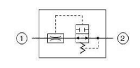
Figure 1: Velocity Fuse Schematic
Applying this hydraulic function to the real world, think about a hydraulic cylinder holding a load at port 1. During normal machine operation and the associated normal flow rates in that part of the circuit, you have the orifice sized so that pressure drop at this normal flow does not cause the valve to shift in the port 1 to port 2 flow direction. But, if you had a sudden catastrophic hose failure like a hose end blowing off or a hose getting cut downstream of port 2, the flow from port 1 to port 2 would suddenly increase dramatically. This would cause the velocity fuse to activate and block flow immediately. This locks the cylinder preventing further movement in that direction.
- For a velocity fuse to work, it requires a significant change in fluid flow.
- If you have a hose that develops a “pinhole leak,” then most likely the velocity fuse will not activate. That type of leak is not yet considered catastrophic.
Sizing a Velocity Fuse
Determine what your normal flow rate is in the port 1-to-port 2 direction. Then choose an orifice size that is about 30% above the flow rate based on about a 50 PSI pressure drop. There are numerous sources for pressure drop curves given a flow rate and pressure drop that corresponds to an orifice size. If you size your orifice too small, you will get “nuisance trips” of the velocity fuse. If you size the orifice too big, it may not work when you need it to. To “reset” the velocity fuse after it has activated, you have to repair the damaged line and move the actuator in the opposite direction. Then it will reset and you can operate normally.
Testing a Velocity Fuse
Once you have chosen your velocity fuse, I recommend you test it to make sure it works when you want it to and it doesn’t work when you don’t. Here’s the method I use, it is very simple. I install the velocity fuse, then I install a TEE in the line between the velocity fuse (port 2) and the directional valve work port. In the branch of the TEE, I install a ball valve rated to handle the working pressure and about double the flow rate of the normal flow for this working line. Then I run a line from the outlet of the ball valve back to the tank (or into a 5-gallon bucket). With the ball valve closed, begin lowering your load under normal conditions. Then quickly open the ball valve (which mimics a sudden hydraulic hose rupture) and see if the velocity fuse activates and locks or catches the load.
Flow Limiters
Flow limiters are very similar to velocity fuses. They activate the exact same way and are sized the same way. The difference is that a flow limiter does not lock and hold the load in case of a catastrophic hose failure. As you can see in the hydraulic schematic below, there is an orifice in the 2 position valve that, upon being shifted, connects port 1 to port 2 via an orificed flow path. This doesn’t lock the actuator but allows the actuator to continue to move at a controlled rate. There are times when locking the actuator may not be the better condition. A continued, controlled movement may be better. In this case, use the Flow Limiter.
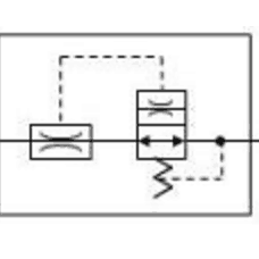
Figure 2: Flow Limiter Schematic
Increase Mobile Machine Safety with Minimal Effort
Velocity fuses and flow regulators are not typically high-cost hydraulic components. Do an evaluation of your machine. Look for ways to make your machine more safe for very little money by using properly applied velocity fuses or flow limiters.