Our experts agree that the most common issues with flow measurement are incorrect sizing of flow meters and poor installation. We’ve seen some pretty creative flow meter piping that totally neglect installation best practices. To ensure that doesn’t happen to you, read below to learn more about proper installation.
Flow Meter Installation
After all, you went through the trouble of selecting the proper meter for your application, why not ensure it’s installed in a manner that will produce optimal measurement results? While quite a bit has changed over the years in flow meter technology; you can’t argue with physics. Fluid flowing through a pipe generally assumes a desirable flow profile at or near the center of the pipe. Flow disturbances (distortion and swirl) can occur when your flow meter is installed improperly, reducing measurement accuracy. Aside from improper sizing, material compatibility, and meter misapplication, a number of issues with flow measurement arise from improper piping practices.
A lot of time, effort, and money can go into the purchase of a flow meter. Often, not as much consideration is given to its installation. Perhaps this is due to limited changes that can be made to existing piping (time and expense), the end user dealing with a technology they are not familiar with and making assumptions based on what they have done in the past, or a mechanical contractor having limited experience with various flow meter technologies, etc.
In this case, when talking about improper installation, we are not referring to improper piping alignment or meter orientation (although both are issues and need proper attention depending on the application). What we are referring to is the placement of the meter in the process piping, and its relation to valves, elbows, strainers, reducers, and a host of other devices that can have an effect on the flow profile.
What we hope to do is give you some key questions to ask, resources to go to, and general guidelines to follow. The old adage “if you don’t know something, ask” applies here. There are no bad questions when trying to determine proper meter placement.
One Size Does Not Fit All
In this case, one technology does not fit all applications. We all have our favorite technology that we swear by, but in this case you can’t fit a round peg in a square hole. Just because you have that spare meter lying in your storeroom doesn’t mean it will be the most suitable. There are many options to consider, especially if you have existing piping that can’t be easily modified.
It’s important to consider the installation and how this could impact the type of meter you choose.
If you find that your flow meter performance is suffering from installation effects, all is not lost. Ideally, the meter could be moved to a more suitable location which would ensure proper upstream and downstream straight pipe. Another option would be to change the type of meter or change to a different design of the same kind of meter. For example, changing from a standard vortex to a reducer vortex.
Upstream and Downstream
As there are multiple flow technologies available, so too are the recommendations for proper meter placement in your process piping. While each manufacturer may have different guidelines, below is a general overview of typical upstream and downstream piping requirements to get you started.
DP
For an orifice plate, the straight run required depends on both the beta ratio of the entire installation and on the type of upstream components in the pipeline. If you are using a ‘standard integral’ orifice plate with an upstream inlet side beta of .4, straight run requirements can range up to 20 straight pipe diameters and 10 straight pipe diameters downstream. However, if you are using a conditioning orifice plate with a .4 beta, straight run requirements range from 2-6 straight pipe diameters.
Magnetic Flow Meters
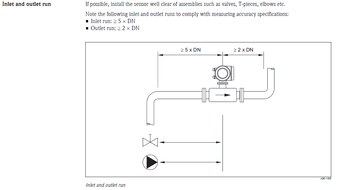
Magnetic flow meters are fairly forgiving in terms of varying flow profile. To ensure specified accuracy over a broader range of process conditions first, ensure that the meter is piped in a manner so it always remains full. Second, install the flow meter a minimum of 5 straight pipe diameters upstream and a minimum of 2 straight pipe diameters downstream from the electrode plane.
Vortex Flow Meters
Vortex flow meters like a fully developed flow profile and typically require long straight upstream piping runs. Elbows, reducers, etc upstream of the sensor will distort the flow profile and so adequate straight runs need to be accounted for. Typical recommendations suggest 35 straight pipe diameters upstream and 5 straight pipe diameters downstream.
If you find that you do not have sufficient upstream straight run, some manufacturers allow for K factor corrections that could reduce this requirement. If using temperature and pressure compensation to derive mass flow, then the temperature and pressure transmitters should be installed downstream of the flowmeter at a minimum of 4-6 straight pipe diameters.
Coriolis Flow Meters
Coriolis flow meters measure mass flow and density directly. Their measurement is insensitive to fluid profile, have very few installation limitations and therefore don’t require upstream and downstream straight pipe runs. The main guidelines for Coriolis sensors are to make sure the sensor tubes remain full. If installed in a vertical pipe, make sure the fluid (liquid and slurries) flow up and gasses flow down and do not use the meter to align misaligned pipe.
Turbine Flow Meters
Turbine flow meters must be installed in a manner that minimizes measurement errors caused by turbulence or damage to the moving parts caused by high flow rates. It is also recommended that a strainer is used upstream of the turbine meter to capture any contaminants that could damage the moving components. Additionally, sufficient back pressure should be maintained to avoid any potential flashing or cavitation.
The general guidelines suggested by manufacturers of turbine flow meters are 15-20 straight pipe diameters (inclusive of the strainer) straight pipe runs upstream and 5 straight pipe diameters straight pipe runs downstream. The upstream requirement can increase if, for example, there are two elbows in different planes (up to 50 straight pipe diameters). Alternatively, the upstream straight run requirement can be reduced if some form of flow straightening is used, down to 10 straight pipe diameters upstream.
Ultrasonic Flow Meters
Ultrasonic flow meters require fully developed flow conditions to ensure the meter will perform as specified. There are two basic types of measuring principles, Doppler and Transit Time, with the latter being more commonly used for fiscal custody transfer applications of gas and petroleum liquids. As with other technologies, these sensors do require adhering to basic installation guidelines to minimize errors caused by flow profile disturbances. However, these requirements vary by manufacturer, which could lead to some confusion; we have seen recommendations as low as 10-20 straight pipe runs upstream.
If this is a fiscal custody transfer application of either a liquid or gas, then make sure you are fully versed with the current standards that are available, in this case the AGA Report No. 9 Measurement of Gas by Multipath Ultrasonic Meters or the API Chapter 5, Section 8 Measurement of Liquid Hydrocarbons by Ultrasonic Flowmeters using Transit Time Technology.
If All Else Fails, Consult the Standards
There are a number of professional organizations that offer guidelines and standards for a majority of the flow technologies being used. Some of these are ISA, ISO, API, AGA, ASME, and ANSI. When in doubt, I would recommend you consult these guidelines as they have been tested and provide a very good starting point to ensure proper flow meter performance. Some of the most common Guidelines/Standards are listed below:
Coriolis – ISO 10790
Critical nozzles – ISO 9300
Differential pressure – ISO 5167
Electromagnetic – ISO 6817
Positive displacement – ISO 2714
Thermal mass – ISO 14511
Turbine – ISO 2715
Ultrasonic – ISO 17089
Variable area – ISO 11605
Vortex – ISO/TR 12764
ASME MFC-3M-2004
ASME MFC-6-2013
ASME MFC-11-2006
ASME MFC-5.1-2011
ASME MFC-16-2014
These are some of the general guidelines to consider when determining proper flow meter placement for your application. By asking the right questions and having a good understanding of the existing guidelines and standards, you should be well on our way to getting the most of your flow meter investment.
Our team of flow experts are here to help you assess your application, determine the right equipment, and determine the best installation for optimal performance. Contact us today to learn more about flow measurement.