100% Employee Owned, Founded 1954

Search
Close this search box.
Cross Logo Horizontal

Three Reasons to Upgrade Pneumatic Valve Manifolds to a Fieldbus System

Contact Today   

With new electronics technology advancements in the Industrial Automation industry, traditional methods of using pneumatic valves in automated machinery and processes are becoming less cost effective and somewhat outdated. We are seeing a shift across the industry that is moving towards fully fieldbus-networked valve manifolds. This new technology provides numerous benefits to OEMs and Custom Machine Builders alike…. Ultimately helping them increase overall profitability and maintain a competitive advantage in a constantly evolving faster, better, cheaper business environment. There are three important reasons why OEMs and Custom Machine Builders should strongly consider upgrading their valve manifolds to a fieldbus system, specifically using Numatics G3 and 580 fieldbus platforms. 

Cost

Let’s start with arguably the most important goal for OEMs… reducing costs. When using a traditional 25-pin or 37-pin ‘Sub-D’ connector kit, dedicated outputs from the PLC are required. Depending on the manufacturer, these output cards can be pricey. This type of traditional valve manifold system is illustrated below in Figure 1. When the ‘Sub-D’ connector kit is replaced with a fieldbus Node, physical output modules are no longer needed to actuate the valves. The fieldbus node connects to the the machine network via an Ethernet switch (shown below in Figure 2) and the outputs become ‘output bits’ in the PLC software. As a rule of thumb, if you have 8 or more valves on your machine, it reaches the tipping point where it is more cost effective to use a fieldbus Node on your valve manifold.. based on hardware cost alone. If you have a 16 or 32 valve manifold, you will likely end up saving hundreds of dollars by making the switch.

Three Reasons to Upgrade Pneumatic Valve Manifolds to a Fieldbus System 1
Figure 1: Traditional Valve Manifold System
Three Reasons to Upgrade Pneumatic Valve Manifolds to a Fieldbus System 2
Figure 2: Numatics 580 Fieldbus System

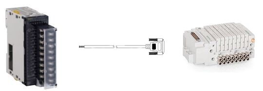
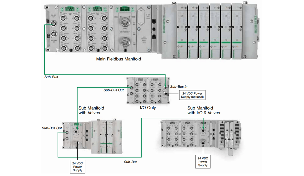
Additional cost savings can be found by using the same fieldbus node controlling the valve manifold to control the inputs and outputs (i.e. sensors, switches, etc.) on a machine. This solution is especially true for OEMs and Custom Machine Builders currently using I/O on a network ‘bus coupler’ or any sort of remote I/O. Numatics G3 Platform allows I/O modules to be stacked to the left of the fieldbus Node, as shown below in Figure 3. These I/O modules come in a variety of configurations (digital I/O, analog I/O, RTD) and have the flexibility to be distributed optimally around the machine. More on that later.

Three Reasons to Upgrade Pneumatic Valve Manifolds to a Fieldbus System 3 
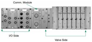
Figure 3: Numatics G3 Fieldbus Network Manifold with I/O Capabilities

Time

It is no secret that if OEMs and Custom Machine Builders can save time, they ultimately add to their bottom line at the end of the year. The faster they can design, build, commission, and ship their machines, the faster they can get paid and build more machines. It is truly amazing the dramatic effect saving a few hours every week can have on sales and revenue growth for the year. So, how does a fieldbus valve manifold help save time?

For starters, by switching to a fieldbus node on your valve manifold, you no longer need to connect each individual valve wire to the PLC output modules. The fieldbus node will plug right into your network switch via an M12 to RJ45 cable. Power is supplied via another M12 connector. It only takes a few seconds to connect the M12 to RJ45 cable to an Ethernet switch. Compare this to the average time it takes to connect each wire to a PLC output card.

OEMs and Custom Machine Builders may be concerned the time saved may be lost in the time it takes to connect the fieldbus node to the machine network and set it up in their PLC software. With Numatics 580 and G3 Platform, the setup is very quick. An integrated LCD screen and two buttons on the 580 and G3 modules make it easy to set the network addressing and connect to the fieldbus network quickly (shown below is Figure 4).

Three Reasons to Upgrade Pneumatic Valve Manifolds to a Fieldbus System 4
Figure 4 Numatics G3 (L) and 580 (R) Integrated LCD Display for Configuration and Diagnostics

Once connected, the configuration of the network (I/O included) is recognized automatically through the integrated web server. Using Numatics supplied EDS, ESI, and other network configuration files, the fieldbus node connects to the PLC as a generic network module. This will import all the status, output, and configuration bits needed to build the machine program. Screenshots from an RSLogix 5000 setup with an Ethernet fieldbus node are shown below is Figure 5.

Three Reasons to Upgrade Pneumatic Valve Manifolds to a Fieldbus System 5
Figure 5 RSLogix 5000 Setup

Wiring time can also be reduced by strategically placing valve, I/O, and combination manifolds around the machine using low-cost ‘sub-bus’ modules. These modules extend the fieldbus network around the machine, allowing a variety of network topologies at a fraction of the cost of a fieldbus node. These distribution options are illustrated below in Figure 6.

Three Reasons to Upgrade Pneumatic Valve Manifolds to a Fieldbus System 6
Figure 6 G3 Platform Distribution Options

Diagnostics

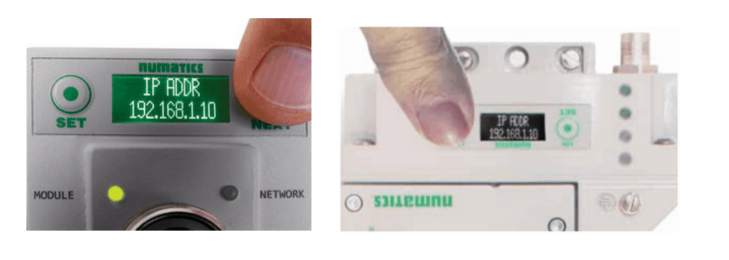
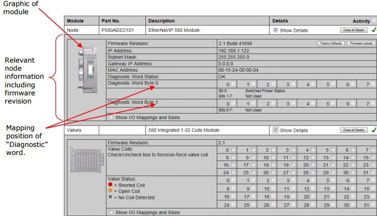
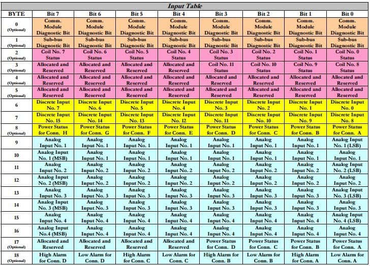
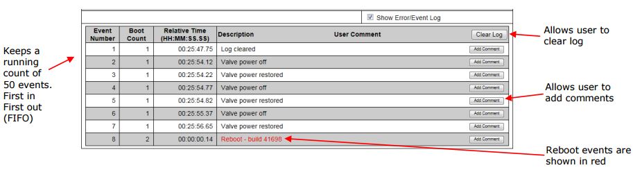
Using a fieldbus valve manifold also unlocks a world of diagnostics not possible with traditional valve connectors. Fieldbus manifolds, like the 580 and G3 platforms from Numatics have the capability to display faults on the integrated LCD display, through the web server, and in the form of ‘status’ input bits to the PLC that can be programmed to pop up on the HMI. This is also true for the I/O modules that can be used in conjunction with the Numatics G3 fieldbus node. The faults include information related to shorted coils, open coils, and valve power failures. The LCD Screen diagnostics are illustrated below in Figure 7.The web server interface and a status input mapping table example are also illustrated in Figure 8 and 9 respectively.

Three Reasons to Upgrade Pneumatic Valve Manifolds to a Fieldbus System 7 
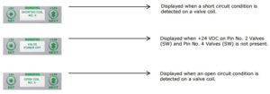
Figure 7 Error Messages


Three Reasons to Upgrade Pneumatic Valve Manifolds to a Fieldbus System 8
Figure 8 Web Server Diagnostics Tab
Three Reasons to Upgrade Pneumatic Valve Manifolds to a Fieldbus System 9
Figure 9 Example Ethernet IP Manifold Status Input Mapping Table

By switching to this technology, frustrating valve and I/O diagnostic procedures can be eliminated. No more grabbing a multimeter to hunt for a valve or sensor with a shorted coil. Having these diagnostic procedures in place can reduce troubleshooting and startup time for both OEMs and Custom Machine Builders. But more importantly, it can reduce costly downtime in the manufacturing process once a machine is shipped to the customer’s facility.

Along with the real-time diagnostics, the Numatics G3 and 580 fieldbus Nodes will keep an error log for any network or distribution errors that arise. The error log can be found in the diagnostics tab of the web server. An example is shown below in Figure 10.

Three Reasons to Upgrade Pneumatic Valve Manifolds to a Fieldbus System 10
Figure 10 Example Error Log

If these three reasons – time, cost and the ability to troubleshoot via diagnostics – have convinced you that you should consider upgrading your valve manifolds to a fieldbus system, the experts at Cross Company would be glad to help!

See how our automation team can help improve quality, increase efficiency, and reduce risk in your operation

Contact our Team

Hang Tight! We're Searching... Searching... Searching...

We’re looking through thousands of pages to find the most relevant information.

In the meantime, enjoy these fun facts…

Did you know… Cross Company is an ESOP (Employee Stock Ownership Plan). Our ESOP started in 1979 and as of 2006, we are 100% employee-owned! Learn more about our ESOP and how that benefits both team members and our customers.
Did you know... the precision measurement group at Cross was founded in 1939 by our current CEO's grandfather, Jim King. That's a whole lot of calibration!
Did you know... A fingerprint weighs about 50 micrograms. We know, we weighed it! The residue left from a finger can actually make a difference in weight results which is why we wear gloves when we calibrate weights. For reference, a sheet of paper is about 4.5 grams, that’s 4.5 million micrograms.
Did you know… Cross Company has grown significantly since our start in 1954. Over the years we've acquired 26 companies! Today, our five groups have expertise in everything from industrial automation to precision measurement, and industry knowledge going all the way back to 1939.