Safety Instrumented Systems (SIS) are installed in Process Plants to mitigate process hazards by taking the process to a “safe state” when predetermined set points have been exceeded or when safe operating conditions have been transgressed.
The SIS is one Protection Layer in a multi-layered safety approach since no single safety measure alone can eliminate risk. A Layer of Protection Analysis (LOPA) is a method whereby all known process hazards and all known layers of protection are closely scrutinized. For each process hazard where the LOPA study concludes that existing protection cannot reduce risk to an acceptable or tolerable level, a Safety Instrumented System is required. Not all process hazards will require the use of a SIS. Each hazard that requires the use of an SIS must be assigned a target SIL level. This article serves as a high-level summary as to how SIL levels are determined for process applications.
What Are SIL Levels?
SIL is an acronym for “Safety Integrity Level” that comes from two voluntary standards used by plant owners/operators to quantify safety performance requirements for hazardous operations:
- IEC 61508: Functional Safety of Electrical/Electronic/Programmable Electronic Safety-Related Systems
- IEC 61511: Safety Instrumented Systems for the Process Industry Sector
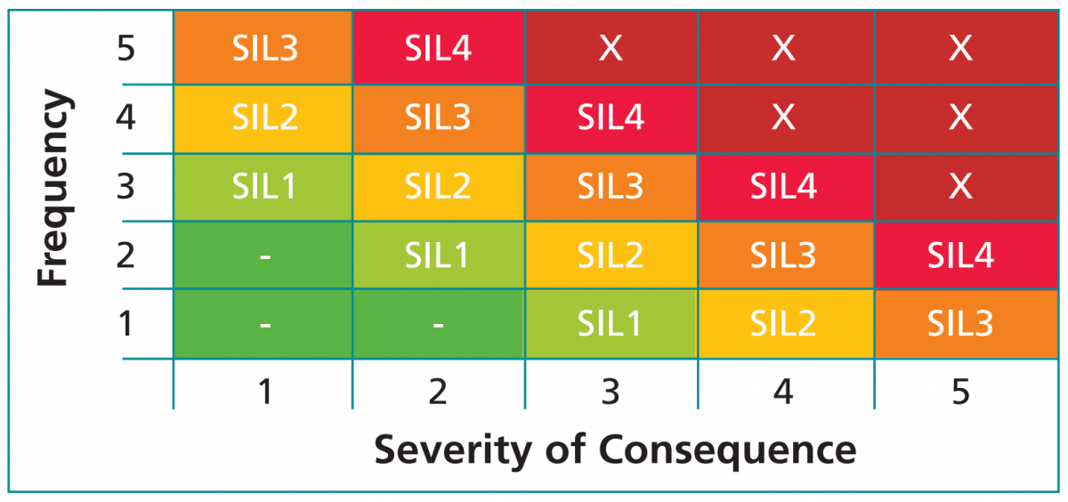
As defined in the IEC standards, there are four SIL Levels (1-4). A higher SIL Level means a greater process hazard and a higher level of protection required from the SIS. To generalize how SIL Level is determined, see Figure 1. SIL Level is a function of hazard frequency and hazard severity. Hazards that can occur more frequently or that have more severe consequences will have higher SIL Levels.
Safety Life Cycle
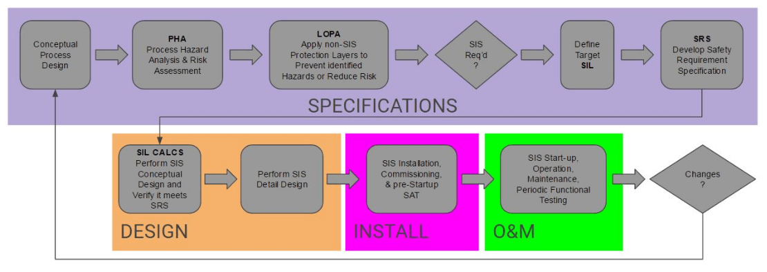
To determine SIL Levels of process hazards, it is helpful to understand the Safety Life Cycle. The IEC standards define a concept known as the Safety Life Cycle, see Figure 2. The Safety Life Cycle provides a repeatable framework whereby all process hazards are identified and analyzed to understand which hazards require the use of a SIS for mitigation. By design, this is a cyclic process, not a linear process with an endpoint. Any changes in process design, operating conditions, or equipment requires cycling back to the beginning to ensure any changes are properly implemented.
Process Hazard Analysis
A Process Hazard Analysis (PHA) is a systematic assessment of all potential hazards associated with an industrial process. It is necessary to analyze all potential causes and consequences of fires, explosions, releases of toxic, hazardous, or flammable materials and more. Focus on anything that might impact the process including:
- Equipment failures
- Instrumentation failures or calibration issues
- Loss of Utilities (power, cooling water, instrument air, etc.)
- Human errors or actions
- External factors such as storms or earthquakes
- And many others
Both the Frequency and Severity of each process hazard must be analyzed:
- How often could it happen? Tank spills could happen any time there’s a manual fill operation (multiple times a year)
- How severe is the result? Localized damage, fire, explosion, toxic gas release, death
Core to the PHA analysis is the fact that things can and do go wrong. You have to forget IF it will happen and instead consider WHEN it will happen. Each identified hazard is assigned an “acceptable” frequency. For purposes of the PHA, you cannot assume a hazard will “never” happen.
- A hazard which results in simple First Aid could be considered “acceptable” if it could happen only once a year
- An explosion and fire due to a tank rupture could have an “acceptable” frequency of once in 10,000 years
The end result of the Process Hazard Analysis is a list of all possible process hazards with each one assigned an acceptable frequency of occurrence. With the PHA complete, the next step in the Safety Life Cycle is the Layer of Protection Analysis.
Layer of Protection Analysis
No single safety measure alone can eliminate risk. For this reason, an effective safety system must consist of protective layers. This way if one protection layer fails, successive layers will take the process to a safe state. As the number of protection layers and their reliabilities increase, the safety of the overall process increases. Figure 3 provides a generalized view of various protection layers. It is important to understand that each layer must function independently from the others in case one or more layers fails.
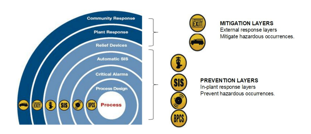
Some specific examples of Protection Layers include:
- Fire suppression systems
- Leak containment systems (dikes or double walls)
- Pressure relief valves
- Gas detection/warning systems
The general steps of a LOPA are as follows. For every Process Hazard identified in the PHA:
- List all available non-SIS safety measures
- Assign each layer its own hazard risk reduction factor
- Calculate an Effective hazard frequency with protection layers applied
Example: A tank fill operation that happens 250 times per year – “could” experience an overfill event 250 times per year.
- A protection layer in the form of a proper vent/drain system could reduce the danger by a factor of 100 (risk reduction factor)
- The hazard resulting from tank overfill would have an effective frequency of 250/100 = 2.5 times per year
After the effective hazard frequency of each hazard is known, the key question to ask is: “With non-SIS protection layers applied, is the effective frequency lower than the acceptable frequency?”
In other words, once all Process Hazards are identified and Protection Layers assigned, if the PHA/LOPA study concludes that existing protection cannot reduce risk to an acceptable or tolerable level, a Safety Instrumented System (SIS) will be required. It is likely you will find that not every process hazard actually requires the use of a SIS.
Safety Instrumented Systems and Functions
The purpose of a SIS is to take a process to a “safe state” when predetermined set points have been exceeded or when safe operating conditions have been transgressed.
The role of the SIS is to reduce risk by implementing Safety Instrumented Functions (SIF). Two example SIFs include:
- Hazard: Tank overfill. SIF: The SIS stops the fill pumps at a predetermined safe level
- Hazard: High temperature. SIF: The SIS opens a relay to cut power to a heater circuit at a predetermined safe temperature
In any case, an SIF is a safety function implemented by the SIS to achieve or maintain a safe state. An SIF’s sensors, logic solver, and final elements act in concert to detect a hazard and bring the process to a safe state.
Each SIF serves as a protection layer to bring the effective hazard frequency down below the acceptable hazard frequency. To do this, each SIF must have a minimum risk reduction factor.
Target SIL Level of the SIF
In our tank overfill example, we determined that after applying non-SIS protection layers we have an effective frequency of 2.5 times per year. If our acceptable hazard frequency is once in 10 years, then the SIF must have a Risk Reduction Factor (RRF) of at least 25.
- Minimum RRF of SIF = Effective frequency w/o SIS / Acceptable frequency = 2.5/0.1 = 25.
- The minimum required RRF of each SIF is used to determine the target SIL Level of the SIF.
Target SIL Level is directly determined from the required RRF by using the table in Figure 4. Note the relationship between SIL Level and RRF. SIL1 has a minimum RRF of 101, SIL2 has a minimum RRF of 102, and so on.
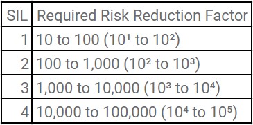
For our tank overfill example, the minimum RRF is 25, the target SIL level of the SIF is SIL1 and this is, therefore, an SIL1 hazard.
For each hazard identified by the PHA and LOPA that requires an SIF, a target SIL level is assigned using the same methodology. Note that it is likely you will have various target SIL levels. The next step in the process is to design a SIS capable of implementing the required SIFs and reaching the target SIL levels.
Achievable SIL Level of the SIF
The SIS is a SYSTEM comprised of numerous components such as:
- Sensors for signal input
- Input signal interfacing and processing
- Logic solver with power and communications
- Output signal processing, interfacing, and power
- Actuators (valves, switching devices) for final control function
An example SIF where the SIS de-energizes a relay to open a heater circuit upon high temperature could have any or all of the following loop components:
- Thermocouple
- Transmitter
- Input signal conditioner or barrier
- Analog Input card
- Communication card(s)
- CPU
- Discrete Output card
- Output signal conditioner or barrier
- Heater circuit relay
In the PHA discussion, we learned that one must assume that a hazard will occur at some point. You cannot assume a hazard will “never” happen. Similarly, one must assume that any of the components of the SIF could fail to act upon demand.
One very common failure would be an isolation valve that remains open under normal process conditions. If this valve is required to close to achieve a particular SIF, it is possible that the valve could stick open and not close upon demand. For this reason, one must know the failure probability the SIF.
The overall failure probability of a given SIF is determined by performing SIL calculations (SIL calcs). SIL calcs are somewhat complex and are outside the scope of this article but essentially, the process is to gather failure rate data for the SIF components and account for factors such as test frequency, redundancy, voting arrangements, etc. The end result is that for each SIF, you end up with an overall Probability of Failure on Demand (PFD).
Failure rate data for the numerous pieces of equipment that can make up SIF loops are published by the equipment manufacturers. Companies frequently contract with consultants such as exida to determine failure rate values.
It is failure rate data that is required as an input to perform SIL calcs for an SIF, not SIL Level data. There is no such thing as an SIL-rated device. We don’t buy SIL-rated transmitters or SIL-rated control systems. We buy components with published failure rate values that are, therefore, “suitable for use in an SIL environment.”
Once the PFD of the SIF is known, then its RRF is simply the inverse of PFD (RRF = 1/PFD). You can then compare the SIF’s RRF to the minimum required RRF. If the SIF’s RRF is greater than the minimum RRF, then the SIF is sufficient to reduce the overall hazard level below the acceptable level.
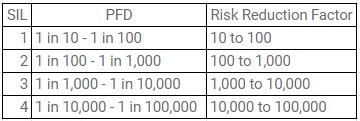
Returning to our tank overfill example, let’s assume the SIL calcs prove the SIF has an RRF of 300. Since this is greater than 25, then the SIF is sufficient. If the SIL calc had found an RRF of less than 25, then changing or rearranging the SIF components would be necessary. One way to increase the RRF is to install redundant transmitters in a voting arrangement or to purchase transmitters with lower published failure rates. The relationship between SIL level, RRF, and PFD is demonstrated in Figure 5.
Returning again to our tank fill example, we had a minimum RRF of 25 (SIL1) with an SIF RRF of 300. The achievable SIL level of the SIF is SIL2. This means we have an SIL2-capable SIF being used to protect an SIL1 hazard. This is perfectly acceptable and is not unusual.
Summary and Conclusion
As we’ve taken a deep dive into safety integrity levels for your process application, here are some of our our top takeaways from the article:
- Process plant hazards become “SIL-Rated” only when existing non-SIS safety layers are insufficient to reduce the hazard to an acceptable level.
- SIL-Rated hazards must be mitigated by SIFs implemented in the SIS.
- The SIL Level of each hazard is determined by calculating the required target Risk Reduction Factor of each SIF.
- Some hazards in your process plant will have higher SIL levels than others.
- To achieve an acceptable level of risk, the SIS must be designed such that each SIF has a PFD corresponding to the required target SIL level.
- There is no such thing as an SIL-rated device or an SIL-rated control system. We don’t buy SIL-rated transmitters or SIL-rated control systems. Instead, we buy components with published failure rate values that are, therefore, “suitable for use in an SIL environment.”
For more information about safety integrity levels and the information discussed in the article, contact a Cross Process Solutions team member today! We have years of experience working in a variety of applications within a range of industries and can help your team determine the best products and solutions for your process. We are proud members of the Control System Integrators Association (CSIA) as well as solutions partners for many leading process equipment and control systems manufacturers, such as Siemens, Rockwell, Honeywell, and many others.