As we’ve explored the guidelines of ISA-88 hierarchy and equipment structure, how can this basis be used to make a flexible design? The answer is very simple: by following the ISA-88 strategy and isolating the Equipment Module (EM) functions into simple and finite processes that encompass all of the possible operating criteria.
Another way to state the overall methodology is to allow the equipment sequencing to be as simple as possible, but to capture every possible option within the sequence. This approach allows the unit operation to have access to all of the possible physical options to achieve the available processing functions. This simplistic approach is outlined below using six strategic design steps that will produce a flexible design. Moreover, the sections below further explain each step to clarify the functional principles of design criteria.
- Define Control and Operating philosophy
- Understand the process before generating a design
- Derive the Control Model
- Use Good Segmentation methodology
- Pay particular attention to exception handling
- Build Test Model Prototype
A flexibly designed batch system consists of multiple aspects of procedural, as well as physical, elements that must be clearly defined and understood in order to define how each will function and handle different occurrences. Considering the complexity of the different layers, the design steps listed below should be executed in the correct order in effort to provide a thorough evaluation. If any single element is either performed incorrectly or not thoroughly, it can potentially have a negative effect on the overall flexibility of the system.
1. Define The Philosophy
The first criteria that must be defined is the control philosophy and overall operating method of the system. This is typically defined within a Functional Design Specification (FDS) document that outlines the level of automation and interaction from the operators. This should also include the exception handling items such as interlocks, unit-to-unit synchronization strategies, continuous monitoring functions, and arbitration methods. This information will provide governing philosophies that will dictate the use and methods of the detail design steps at a later time.
2. Understand the Process
Once the control philosophy is clearly defined, the next step is to fully understand the process. This is a broad term that encompasses the procedural model of how the process functions are executed, and the physical interactions with the equipment. This knowledge base can be derived from a combination of documents and conversations with key operational personnel. Typical reference documentation includes, Process Flow Diagram (PFD), Piping & Instrumentation Diagrams (P&ID), Standard Operating Procedures (SOP), process descriptions, and control system narratives. Each supporting document provides a different aspect to explain the overall production process. This information will become invaluable at a later time when determining the operator interface requirements.
3. Derive the Control Model
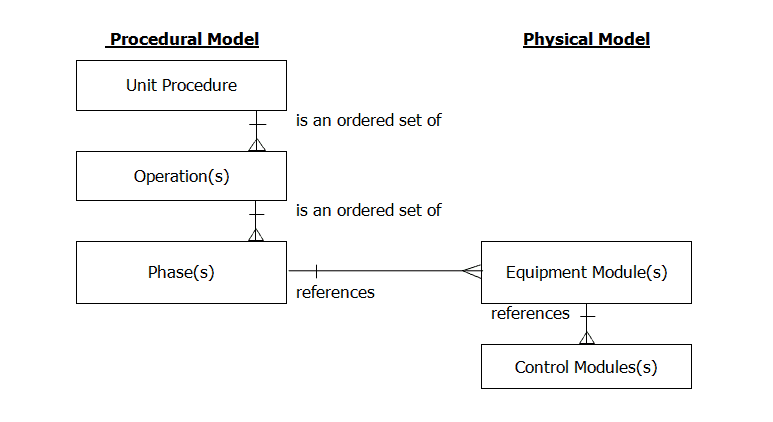
At this point, the control capabilities, operating philosophies, and how the actual production process works is fully understood. Given this information, the Control Model needs to be derived to identify the interactions between the physical and procedural models. The procedural control directs the equipment-oriented action to take place in an ordered sequence to carry out process oriented tasks. This can be designed using several different philosophies and all of them within the ISA-88 structure. However, to achieve a flexible design, it is important to enable the equipment functions easily within the procedural layer. Figure 1 below includes a typical Control Model that depicts the relationship between the procedural and physical model.
The procedural model defines a set of tasks that are used to carry out actions, also known as a strategy, for making a product. A procedure consists of an ordered set of operations, which are called phases. A phase is the smallest element of the procedural control that can be used to accomplish a process oriented task. The figure above shows that phase(s) are linked to equipment specific commands.
4. Use Good Segmentation Methodology
Segmentation is an important aspect when designing a flexible system, which includes unit boundary definitions as well as Equipment Module partitioning within the associated unit. These two segmentation decisions work hand-in-hand. Poor segmentation in either aspect results in the following:
- Control system is difficult to support and enhance
- System fails to exploit the inherent flexibility of the plant
- New recipe development requires the assistance of control system developers
- Equipment faults and/or Error handling is difficult to determine when running a batch
Unit boundary definitions typically follow the physical model. However, the criteria for defining the unit boundaries should adhere to the following principles:
- Centered around a major piece of processing equipment
- Frequently operates on, or contains, the complete batch
- May operate on, or contain, only a portion of the complete batch
- Cannot operate on, or contain, more than one batch
- Must have direct relationship with procedures and operations
- Verify unit boundaries against the procedural elements (from control model)
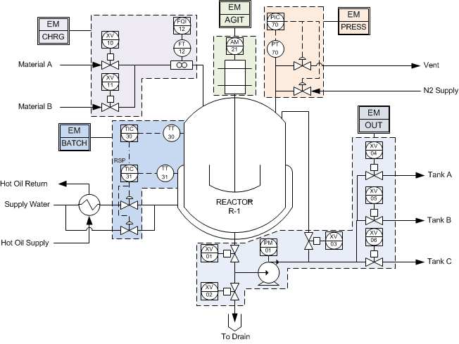
Once the unit boundaries are identified, the EM’s can be partitioned into self-contained equipment entity groups. The grouping of CM’s should be governed by the physical processing constraints. This means that equipment limitation will dictate the segmentation. An example of physical limitation would be a shared piece of equipment, such as a bottom pump that can be used for recirculation, as well as material transfer to another unit. When partitioning the EM’s within a unit, the following criteria shall be applied:
- Purpose – all elements in the module must support a similar processing purpose and be self-contained
- Portability – the module must be reusable
- Flexibility – design the module so that it is not limited and can perform all of the available processing functions
- Independence – must have the ability to operate on its own without other EM interactions
- Some strategies will require interaction, such as transfer or material routing
- Specify the relationship and communication between the equipment entities (be consistent)
- Expansion – have the ability to add additional capacity by adding other CM’s
- Isolation – ability to minimize the effects of process exceptions by containing them within the module
- Verification – Verify the EM boundaries against the defined procedural elements (from control model)
Segmentation is a very important design step that requires knowledge of processing equipment, process operation requirements, and interactions from upstream and downstream equipment. These steps should be cross referenced with all requirements to ensure the design is robust enough to handle all the processing activities. The figure below depicts a simple example of a batch reactor and the EM partitioning.
5. Pay Attention to Exception Handling
An exception is an event that occurs outside of the normal or desired behavior. The most challenging part of designing most batch systems is the handling of these occurrences, which can occur at all levels of the control activity model. All exceptions must be detected, evaluated, and responded to. The location of where to implement the response depends on where the issue was detected, and the reaction required to correct the situation. Typically, the exception response propagates up the control activity model, which is built into the base ISA-88 model recipe systems. However, depending on the specific situation, the response may also propagate down the control activity model to correct the issue.
In effort to discern the differences of the exception handling execution, the types of conditions must be categorized and prioritized to determine the correct actions. The categories and examples of each are listed in the bullet points below.
Process Interlocks – Priority 1 (highest)
- Implemented at the CM level
- Safety conditions determined by performing a Process Hazard Analysis
- e.g. Pressure switch high-high (PSHH1201)
Operating Conditions – Priority 2
- Implemented at the EM level
- Critical operating parameters typically configured as EM parameters; usually associated with product quality
- e.g.TIC high deviation > 1 minute
Unit Conditions – Priority 3
- Implemented at the Unit level
- Execution parameter typically associated with coordination and/or synchronization
- e.g. Transferring material and downstream unit is not ready to receive material
Procedural Conditions – Priority 4
- Implemented at the recipe level
- Monitoring condition can range from overall product quality and/or equipment coordination
- e.g. During the temperature ramp up phase the NIR feedback shall hold the ramp if outside of acceptable range
Process interlocks shall always be the highest priority within a Basic Process Control System (BPCS). The only item that will have a higher priority is a Safety Instrumented System, which would be executed at the CM layer as well.
Operating conditions are typically derived from quality critical parameters, and are assigned as equipment parameters in effort to manage these at the procedural level using a formula chart. Unit conditions include a higher level of interaction or coordination that typically include physical execution constraints of the associated system. The lowest priority of execution is at the procedural level, which can execute an additional set of ordered phases based on the condition feedback from the process.
The corrective actions for each level can propagate both up and down, based on the requirement. An exception always has an effect on the next level above where the issue occurred. As an example, if a pump fails during operation, the CM will propagate the error to the associated EM, which may or may not propagate to the unit. This may or may not impact the overall recipe, depending on the design, as well as when the issue occurred during the execution of the batch. Figure 3 below depicts the overall bi-directional interaction between the associated layers.

Exception handling can become very complex and it is best to keep the interactions as simple as possible. The key to minimizing the confusion is to assign the correct action at the proper layer to ensure safety and production quality are maintained. Exception definitions and configuration can take up as much as 40% of the overall implementation time of the project!
A typical pitfall during a design process is to confuse the exception priorities. Exception handling is not an after thought, but the base equipment sequencing must be designed first to identify all of the exception conditions. This task is critical and time consuming, but it is essential for a successful project.
6. Build Test Model Prototype
One of the most underestimated stages of a project is the testing phase. This step is a crucial piece of the workflow process to ensure all aspects are collectively working together and interacting as expected. The idea is to interject any and every possible aspect, event, and/or condition possible to be able to predict the behavior of the system. Essentially, this is the last step to catch and correct any type of nuance or issue that may have been overlooked when developing the functional specifications.
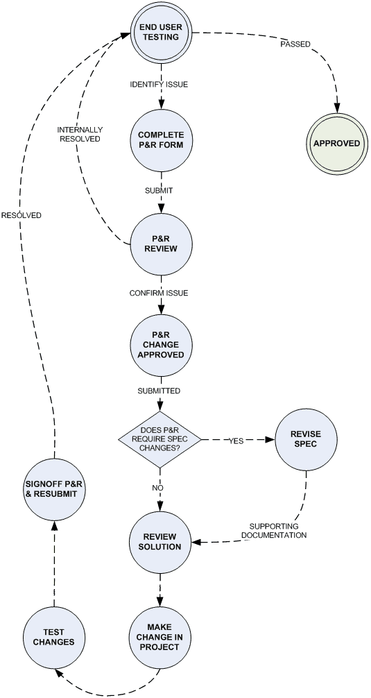
To manage a project effectively, it is essential to have an overall plan in place to define exactly how the system is going to be tested. In addition, when issues are identified during the execution of a test, a series of events need to be defined to resolve and/or correct the issues at hand. Basic test documents typically refer back to the detail specifications to ensure the requirements are satisfied. Figure 4 below depicts a typical testing procedure outline using a Problem and Resolution (P&R) form. This method helps track the issues and provides an overall system for handling and resolving the issues.
In summary, the ISA-88 standard provides a flexible set of guidelines to apply a design concept for almost any manufacturing process. The standard is adaptable enough to be implemented using several different philosophies, all within the defined structure. To develop a robust system, it is essential that the correct design steps are implemented to fully understand the interactions. Standardizing the equipment level simplifies the upper level process control functions within the batch so that non-control engineers can manage the process successfully.
The benefit of implementing a robust design standard provides the tools necessary to increase production efficiency, such as cycle time, product quality, and maintainability. Thus the overall result allows production engineers to implement continuous process improvement objectives to achieve the full potential of the processing system. Work with the team at Cross to design a flexible control system that improves efficiency and reduces risk in your process.
How Cross Can Help
Cross Company Process Solutions is an authorized Solutions Partner, recognized Systems Integrator, Manufacturer’s Representative, and value-added Distributor for process manufacturers in a wide range of industries. With our focus on systems integration, process instrumentation, valves and valve repair, and many other full solutions, we can ensure your facility is running the way you need it to. Check out our products, services, and solutions to see how we can add value to your process.
As members of the Control System Integrators Association (CSIA) as well as certified solutions partners for ABB, Honeywell, Rockwell, Siemens, and VTScada, Cross Company has the the experience and expertise to optimize your process. Contact our Process Solutions Group today to learn more or to get started.