Knowing the do’s and don’ts of oval gear flow meter installations is just as important to the life of your meter as was the selection criteria for choosing an oval gear flow meter. To avoid any unintentional damage to your new oval gear flow meter, just prior to installing would be a great time to double-check on several crucial parameters that could have been overlooked during the selection process.
Flow rate, system pressure, system temperature, and chemical compatibility are the most likely culprits when it comes to unintentional damage to your flow meter at start-up. Other things to check are fluid viscosity, particle content in the line, fluid state, and any regulatory requirements that need to be met if the installation is in a hazardous area.
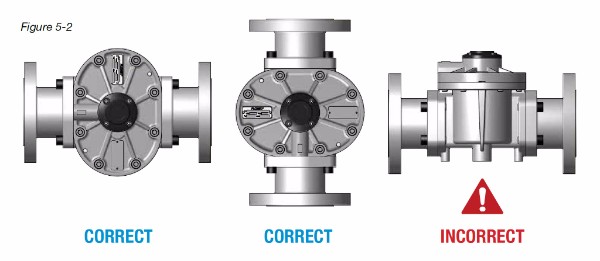
Orientation
Failure to mount your oval gear meter in the correct orientation (see figure 5-2 below) will cause the weight of the rotors to bear down on the thrust bearings, and on the floor of the measuring chamber. The short term effect of incorrect mounting orientation will be a loss in accuracy. Long term effects range from reduced lifespan (for very small meters) to significant damage to bearings, rotors, and the measuring chamber (for the largest meters). Liquids can flow in a horizontal direction, or a vertical (up) direction, but in each case, the rotor shafts must be in a horizontal plane. This is achieved by mounting the meter so that the terminal cover, or integral instrument display, is facing in a horizontal direction as shown below.
Flow Direction
Pulse-type oval gear meters are bi-directional and will measure flow in either direction, without distinguishing the actual direction of the flow.
Mechanical-type oval gear meters can only measure flow in one direction, and that direction will be indicated on the body of the meter. Failure to adhere to the orientation on a mechanical flow meter will cause the mechanical counter to operate in reverse. Reverse operation for an extended period of time may cause permanent damage to the mechanical counter mechanism.
Piping Construction
To avoid damage to your flow meter it is recommended that the following points be considered when designing/constructing your piping system:
- Never install a medium or large capacity oval gear meters on the suction side of a pump. Systems can be designed to safely and accurately operate a small oval gear meter on suction (3/8″ size or smaller meter).
- System pressure and temperature must stay within safe limits. Install oval gear meters upstream of a flow control or shut-off valve. The back-pressure provided by the valve will be beneficial to system accuracy.
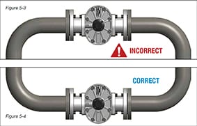
- For vertical installations, the liquid should travel from bottom to top. This will ensure that the flow meter remains full of liquid, and will prevent air entrapment in the meter. Piping should be designed so that the flow meter is full of liquid at all times. The inlet and outlet piping for the flow meter should be higher than all surrounding piping.
- All piping surrounding your flow meter should be well supported where the piping joins to the flow meter. This is particularly important with 2″ and larger flow meters.
- Operating a flow meter directly discharging to the atmosphere is not advisable, as it will be detrimental to accuracy.
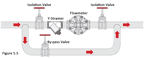
If your flow meter is installed between two shutoff valves, it will be necessary to install pressure relief valves, or thermal expansion joints to protect from high-pressure conditions due to temperature change. It is always important to provide a bypass line (see figure 5-5). This provides isolation of the flow meter and strainer from the main process line. This allows quick and easy cleaning of the strainer, as well as easy maintenance and repairs on your flow meter.
Filtration and Straining
You must be sure your liquid is clean and 100% free of foreign particles to properly protect an oval gear meter. Solid particles can be present in a system from a number of sources:
- Dust settling on unsealed storage tanks
- Wear on upstream mechanical devices such as pumps or mixers
- Large metal particles from cutting or welding on new or modified installations
You should install a filter or strainer on the inlet side of an oval gear meter.
- Small oval gear meters, 1/8″ to 3/8″ (4 mm to 8 mm), require a 200 mesh strainer.
- Medium oval gear meters, 1/2″ to 2″ (15 mm to 50 mm), require a 100 mesh strainer.
- Large oval gear meters, 3″ to 4″ (80 mm to 100 mm), require a 40 mesh strainer.
The Y-type strainer is the most common choice as it is the lightest, smallest, and most economical. It also produces minimal pressure loss.
Air Elimination
It’s very important to note that oval gear meters cannot differentiate between liquid and gas. The presence of air bubbles or vapor in your liquid will cause measurement errors as well as damage to your flow meter.
If air or vapor in your low viscosity liquid, cannot be avoided, an air eliminator strainer (AES) is recommended. The AES should always be installed upstream of the oval gear meters. The AES is capable of capturing and venting large amounts of air that are found with the initial filling of the system.
For high viscosity liquids (> 100cP), or applications where large amounts of air need to be removed from the flow stream, a large capacity AES is required. The large AES should be installed immediately downstream of a high-capacity air separator tank. The air separator tank provides the necessary time for viscous liquids to release the entrained air or vapor prior to entering the flow meter.
Start-Up Procedures
The most common cause of damage to an oval gear meter is due to the use of improper start-up procedures after installation, modification, or after long periods of shutdown. This is because new or modified piping is generally full of large volumes of air.
The newly installed meter must NOT be run until the piping is completely flushed of foreign materials. The most common foreign matter that is present in new or modified piping is welding slag, grinding dust, sealing tape/ compound, or surface rust. If your meter has been installed with a bypass line it will be easy to isolate your flow meter from the remainder of the system in order to flush out the majority of the piping.
If you have not installed a bypass line around your flow meter, the best solution is to replace your meter with a spool piece for the duration of the flushing procedure. Following the start-up procedure, and during the period of initial operation, it is recommended that the inlet strainer on your flow meter be inspected regularly.
Maintenance and Cleaning
An oval gear meter is a mechanical device, and as such is subject to some wear and tear over its life. In order to maximize the operational availability of your meter, and reduce system downtime, a periodic maintenance and inspection program should be implemented. The amount of normal wear that the meter will experience will depend on several factors.
- Flow rate
- Process temperature
- Fluid cleanliness
- Fluid lubricity
- Continuous duty run time
Before beginning any flow meter maintenance, ensure the following items have been completed:
- The flow line and flow meter have been shut down, de-pressurized, and drained of all liquids
- Associated alarms, control outputs, etc. have been isolated so as not to affect the process
- Any power supply/voltage supplied to the meter has been isolated and/or shut down
Periodic maintenance and inspection should occur every six to twelve months, especially for installations in harsh conditions. Specifically in applications with:
- Large temperature variations
- Long periods of flow greater than 80% of the meter’s maximum continuous flow rating
For any installations that require CIP (clean in place), it is important that the cleaning or flushing procedures do not exceed the advertised operating specifications. CIP procedures that increase system temperature at a rate greater than 50°F (10°C) per minute may damage the reed switch output. Chemical compatibility of cleaning solutions should also be checked against the flow meter materials of construction.
Calibration
Each flow meter is individually calibrated at the factory and then supplied with a calibration certificate showing the number of pulses per unit volume (for a pulse output meter) or the nominal reading error (for mechanical meters).
Factory calibrations are done using the master meter method, using Castrol Diesel Calibration Fluid 4113. For measurement of any liquids significantly similar to Diesel Calibration Fluid 4113, that is lubricating and with a viscosity of between 3-100cP, there will be no loss of flow meter performance when using the factory calibration factor.
For any liquids where the viscosity or the lubricity of the liquid varies significantly from the factory calibration liquid (viscosity less than 1cP, or greater than 1000cP), it is advisable to recalibrate your flow meter on the liquid that will be measured. For any field calibration of your oval gear meter it is important to consider the accuracy of your calibration procedure, and of your volume standard:
- Calibration of your oval gear meter using a poorly controlled procedure, or using a volume standard of unknown accuracy will produce poor results.
- Any calibration procedure should be run for at least 2 minutes in order to reduce the impact of start-up and shut-down flows on your readings
Possible volume standards that can be used for field calibrations are:
- Scales – Although this is the most common calibration method, it can also be one of the least accurate. Scales must be recently calibrated to ensure accuracy, and must have fine graduations in order to achieve the required measurement uncertainty.
- Master Meter – The master meter method is the most common volume standard used for factory calibration of PD flow meters, which is due to its accuracy and practicality.
- Volumetric Calibration Container – This method is typically considered to be the least common and most impractical method. Ironically, it’s the most accurate.
Electric Installations
The main factors to consider when electrically installing a pulse output flowmeter are; the type of output signal you require, the quality of the wiring connections, and any local regulatory requirements. Two types of output are available on every standard pulse output oval gear flowmeter; NPN Hall effect and Reed switch (contact closure). Each output type is linearly proportional to volumetric flow and each pulse is representative of an equal volume. Both outputs have their own advantages and disadvantages, and depending on the system requirements, your flowmeter may be installed using either output, or both outputs (wired to two separate instruments).
Hall Effect Outputs
The NPN Hall effect is a high-resolution solid-state three wire device which provides an unsourced, open collector, NPN transistor output. The term unsourced means that no voltage is applied to the output from within the flow meter. The output of the Hall effect must be pulled to a ‘high’ state by an external voltage between 5-24VDC, this is achieved by fitting a pull-up resistor between the signal output and the voltage supply. The pull up resistor ties the open collector output to the available DC voltage level, providing a square wave pulse output, which alternates between ground potential and the DC voltage available at the signal terminal.
The NPN Hall effect output is a reliable output type, producing a consistent output irrespective of supply voltage variations, temperature variations, or mechanical shock. As the Hall effect output does not rely on a mechanical device, the service life of this output is theoretically infinite. The Hall effect output should be preferentially chosen whenever a power source is available.
Many secondary flow instruments are fitted with an integral pull-up resistor, but if connecting the Hall effect output to an electronic device that does not contain an integral pull-up resistor, one must be provided. The pull-up resistor should be sized to limit the Hall effect switching current to less than 10mA; in order to achieve this, use Ohm’s Law to calculate an appropriate pull-up resistance to suit your power supply voltage and current requirements. The recommended minimum pull-up resistor value is 2.4 kOhm, however much higher values of 10 kOhm are more commonly used.
The total current draw of the Hall effect output is nominally 20mA plus your switching current. If a 24V power supply is used with a 10K Ohm pull-up resistor, this equates to approximately 23mA.
When installing your Hall effect output, the most critical consideration is the quality of the voltage regulation and the type of loads present on any common voltage sources. It is NOT recommended to combine any inductive loads on the same voltage supply as your flow meter, as these components are commonly sources of high-frequency interference that may affect the quality of the Hall effect output signal. Another concern is the potential for voltage spikes well in excess of the 24VDC limit of the Hall effect sensors.
Hall Effect Faults
By far the most common cause of a Hall effect fault is electrical damage caused by incorrect wiring, voltage spikes, or short circuits. As Hall effect sensors are solid-state devices their failure tends to be sudden and permanent. Unlike the Reed switch, the Hall effect sensor will completely cease to function once damaged and tends not to produce intermittent or gradual failures.
Visual inspection of the Hall effect sensor will usually show if a failure has occurred (although not always). Overvoltage, reverse polarity, or short circuits will usually create visual damage and a smell of burning. A failed Hall effect sensor can only be fixed by replacement of the pulse output board.
Testing With an Oscilloscope
An oscilloscope is a useful tool that can be used for more advanced pulse output board troubleshooting. However, it requires a greater understanding of electrical signals in order to be useful. An oscilloscope is most useful for detecting the presence of an output signal, and can give information about the quality of the signal that will allow diagnosis of some output problems without disassembly of the mechanical parts of the flow meter.
PC oscilloscopes can be particularly useful when compared to regular oscilloscopes; as signal traces can be saved as image files (JPEG or similar) and emailed to a technical sales representative for help in troubleshooting your signal output issues. Economical single-channel PC oscilloscopes can be purchased that will interface with any USB capable Windows PC.
Rotating the Mechanical Register
The mechanical display can be rotated in increments of 90 degrees to suit the orientation of the flow meter in your installation. Note that the flow direction of the flow meter is set by the gearbox. The flow meter must be installed with the correct flow orientation marked by the arrow on the meter, then rotate the display to allow the operator to read the digits.
Noisy Meters
Oval Gear meters are typically designed with just two moving parts. Under normal circumstances, those gears will emit a revving sound during operation of the meter and that sound can vary based on the rotor material and size of the flow meter. If that sound increases over a period of time, it’s very likely that small amounts of debris/foreign particles have built up in the process lines leading to the flow meter and they in turn create a rattling sound inside the meter’s measuring chamber. The obvious solution to this problem is to clean the filtration system leading up to the flow meter to ensure the cleanliness of the fluid as it enters the flow meter. It’s also highly recommended to inspect the measuring chamber and rotors for any foreign debris and resulting damage.
- Should excessive wear be found on the rotors in the form of chips in the gearing or score marks etched across the top and bottom of the rotors, then it’s recommended that you replace the rotors to ensure the integrity and accuracy of the meter. It’s also important to ensure that no further damage is done to the walls of the measuring chamber. If excessive damage is found in the measuring chamber, this could result in noise and/or accuracy issues. In most instances, damage to the measuring chamber will require replacement of the flow meter.
- Cracks or bearing failure within the rotor can result in abnormal movement and ultimately, can cause the rotor(s) to hit the wall of the measuring chamber. Upon inspection, there should be no lateral movement of the rotor in relation to the rotor shaft. In any of these instances, new rotors will be needed. Note: Rotors and Bearings are purchased as a single item.
- If noise is an issue due to previous damage or high flow rates, it is recommended to install PPS rotors where the application allows it.
- Meters will run louder when the meter has no fluid in it and is having large amounts of air rush through it. This is not recommended as this can cause excessive wear on the bearings and cause them to fail.
No Flow / Low Flow
When a “no flow” and/or “low flow” condition is detected, the first thing to check is whether or not the meter has been installed correctly, as outlined in the operations manual. If the flow meter has been installed correctly, with an adequate flow that meets the flow meter’s minimum flow requirements, the next thing to check would be external components within the process that could have an effect on the flow, such as a faulty pump, a valve that is not functioning correctly or a blocked/clogged strainer upstream of the meter.
If these external components are clear, the next most likely cause would be a malfunctioning rotor. Rotors subjected to “dirty” fluids can seize if foreign particles are caught up between the individual gears. This condition can also damage the rotor bearings which will eventually also cause them to seize. Damage to the rotors and/or bearings necessitates an inspection of the measuring chamber for any resulting damage that may cause noise and/or damage to replacement rotors.
Other causes resulting in jammed and/or damaged rotors include:
- Chemical incompatibility (this happens more with PPS rotors than stainless steel).
- Rapid temperature changes causing the rotors to expand before the meter body can adjust.
- Rotor pins distorting due to overpressure causing the rotors to shift their angle inside the measuring chamber and seize.
- Process fluids drying/curing.
- Bearing failure due to over speeding which is caused when the flow rate is higher than the meters tolerances allow.
- Bearing failure can also be a result of air not being bled from the piping during installation or at any time where the piping is drained between meter use.
Register Issues
Issues with mechanical registers are rare, but not unheard of. They typically come as a result of maintenance or other tampering once the register assembly has been opened. Typical register issues include:
The gasket seal can be inserted upside down. If reinstalled incorrectly, the register assembly will hold any unwanted fluids and/or air inside it, especially if the installation is outside and/or in an extremely dusty environment. It’s important to note that this will not cause any mechanical issues for the meter, but can make it difficult for the operator to read the display.
Opaque screen. In some applications, the polycarbonate lens on the screen can become distorted making it difficult to take a reading. This is particularly noticeable measuring fluids like Ethanol, Turpentine, etc.. Should this happen, a new screen will be required and appropriate actions will need to be taken to prevent this from happening again in the future.
Should any leaking occur from the area between the register assembly and the meter itself, resulting in the fluid entering the register assembly or leaking outside the meter, a new register plate will be required.
Work With an Expert
If you are experiencing issues with your oval gear flow meter we encourage you to reach out to one of our flow experts. While this guide is intended to help you install your meter correctly and troubleshoot common issues, this is not an exhaustive list. Please contact us today to discuss your application and specific issues you may be having with your flow meter.