When setting up a low pressure storage tank, there are a number of safety devices needed to ensure the protection of your tank including an ERV (Emergency Relief Valve), a PVRV (Pressure and Vacuum Relief Valve) and a BGR (Blanket Gas Regulator). For illustration purposes, we will walk through the proper set up of an API 650 storage tank so that one safety device doesn’t interfere with the next.
Please keep in mind that this is an ideal tank scenario where we will allow ourselves to have 100% over pressure availability. We recognize that this is not always going to be the case.
API 650 Tank Application
For these types of applications, there are typically two types of tanks seen the most in the field. They are the API 620 and the API 650 tanks. For this discussion, we will be utilizing an API 650 tank. These tanks are normally rated at about 2.5 psig or less. The MAWV (The maximum allowable working vacuum) is normally something less than 2.5 inwc. What you see below is a basic set up.
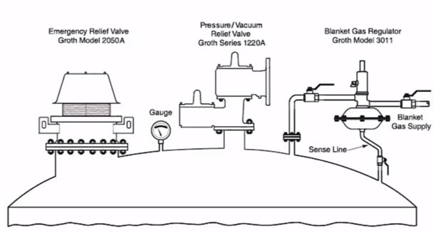
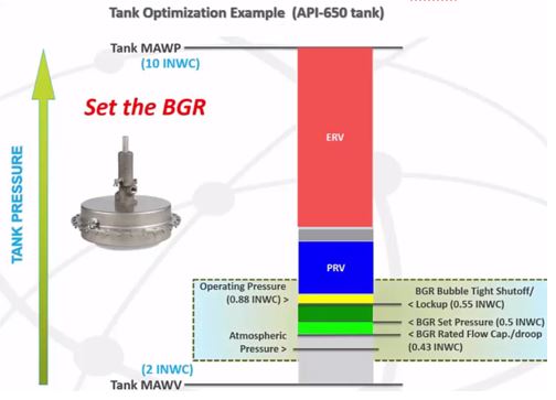
In the middle of the picture we have a PVRV and to the right of the PVRV is a BGR. For those of you who don’t work with BGRs on a regular basis, it is used to provide an inert gas in the vapor space over the media in the tank whereby limiting potential flammability.
On the left side of the picture you’ll see the ERV. A common problem in the field is when the ERV is set too close to the PRV. This causes the ERV to open when it shouldn’t. It is VERY important that the ERV only open in the case of an upset condition.
To get us started, we will simplify the tank optimization process by drawing a capital letter “I” on a piece of paper. At the top of the I, write in the tank’s MAWP (Maximum Allowable Working Pressure) and at the bottom, the tank’s MAWV (Maximum Allowable Working Vacuum). These two items are very important. Without this vital information, no one should ever offer you any type of valve quote. To guess on such an issue would be a serious liability to both the supplier and the customer
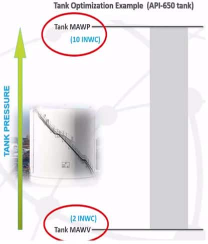
MAWP and MAWV
First let’s focus on the MAWP and the MAWV. For reference and in this instance we’re going to use 10 inwc for the MAWP and 2 inwc for the MAWV. From there begin filling in all the spaces in between.
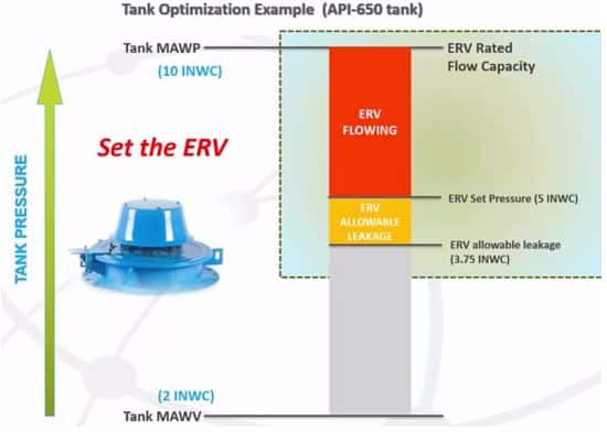
Let’s start with the ERV as it is set closest to the MAWP of the tank. With 10 inwc, where to do you suppose we set the ERV? In this instance we will set it at 5 inwc understanding that doubling the set pressure will give us full flow. Our goal here is to achieve full flow before we reach the MAWP of the tank. Something very important on these API 650 tanks is that the flow and pressure cannot exceed the MAWP of the tank. On a 620 tank, the rules are a little different but for this example our goal is to reach 10 inwc before we reach the MAWP. With that in mind, this is pretty cut and dry… 5 inwc with double the set pressure equals 10 inwc. No problem right?
This is the area where most people get into trouble. They fail to consider that with this type of valve, it actually starts to open or crack at about 75%-80% of set pressure. So in this scenario, the valve will actually begin to open at about 3.75 inwc. This is a very common problem if you’re used to sizing for a section 8 valve. Those valves are set at the rated and MAWP of the tank so it goes off all at once. Low-pressure storage tank valves obviously don’t operate in that way. You must always allow for this 75% overpressure and double the set pressure to achieve full flow.
PRV
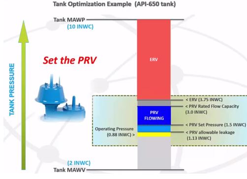
The next item we’re going to optimize on our tank is the PRV. In this instance, you have hypothetically given us .88 inwc as your operating pressure. This number will always be pre-determined by you.
What we will do here is set this PRV at 1.5 inwc which is above the .88” working band. Again, the reason we do that is because we are looking for double the set pressure which would take the 1.5 inwc to 3 inwc.
In the picture above, you’ll notice that just above the PRV (flowing in blue) there is a dead spot. That space is necessary so that the ERV will not be triggered if the PRV is flowing at 100% overpressure. With the ERV beginning to open at 75% of set, in this scenario you have .75in available before the ERV will start to open. API code does not state how much that dead space should be. However, just keep in mind that the ERV should not start to open until there is truly an upset condition.
Customers often ask what that dead space is doing during an upset condition. Basically the PRV will be fully open and will fully flow. It will surpass that .75in dead spot and the ERV and the PRV will begin flowing in tandem. It is important to understand that at this point both valves are now working together.
With the PRV set at 1.5 inwc, with full flow at 3 inches, taking into account the allowable leakage rate. This PRV at 75% of set is going to begin to crack or open at 1.13 inwc. This is still above the normal operating pressure. The goal is not to have the valve open at the normal operating pressure.
BGR
The next step in optimization is the BGR. Not all tanks will have BGRs as this is subjective to your wishes. BGRS are normally going to be set above atmospheric pressure. So in this instance we’re going to set the BGR at .5 inwc. There is basically a 10% dead band, known as lock up and droop, on either side of the BGR. So if we set it up at .5 inwc, you know that this will lock up or bubble tight shut off at a .55 inwc, which is still under the PRV setting.
One of the major concerns of customers is that they are constantly venting nitrogen. What might actually be happening is the PRV is set way too close to the operation of the BGR. At .55 inwc you will no longer have any flow of nitrogen into the system. The PRV will not begin to crack until it gets to 1.13 inwc so that is now a non-issue.
The droop, which is the other side of the dead band, should also be roughly about 10%. In this instance we know it is around 0.43 inwc. Again we want to adjust the valves around this BGR and normal operating conditions so there are no concerns about venting nitrogen to the atmosphere.
Vacuum Relief Valve
Finally, let’s look at the Vacuum Relief Valve. In this instance, we know we have a 2” MAWV. So it’s clear to see that if we are at 100% overpressure, we will need to set the vacuum relief valve at about 1 inwc so I have full flow at 2 inwc. Again, don’t forget that the valve starts to open or crack at about 75% of set and in this instance it would be about .75 inwc. We always need to take these variables into consideration.
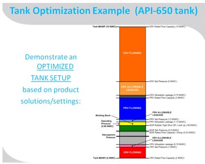
To the left is the overall picture for optimized API 650 tank.
Obviously, your tank could take on different scenarios than which I present. For instance, you could be using a pilot operated valve. In that scenario the valve can flow at 10% overpressure at full flow. You could then set the pilot operated valve much closer to the MAWP of the tank.
Obviously your tank could take on different scenarios than what is discussed above. For instance, you could be using a pilot operated valve. In that scenario the valve can flow at 10% overpressure at full flow. You could then set the pilot operated valve much closer to the MAWP of the tank.
You will likely never have the ability to use 100% overpressure at all times. In many instances, you may be trying to fit different devices into a small area or trying to operate at 20%, 30% or 40% overpressure.
API 620 tanks have a separate set of ground rules as there is an additional 20% over pressure that is allowed above and beyond the MAWP as a safety factor. However, by putting your information down in an “I” picture format, you can quickly visualize and understand what you can and cannot do on your tank.
If you have any questions or would like additional information, we have a team of safety experts available to help you optimize your low-pressure tank. In addition, we offer a Tank Optimization Program (TOP) which is a full audit of your tank accessories to ensure proper function. Contact us today to learn more.