So, you’re going to use an AC drive and you know what horsepower and voltage you need, now what? There are numerous issues to consider when applying an AC drive. Take a look some of the most common topics we get asked about.
Control Modes
There are three different motor modes available with AC drives:
1. V/f (Commonly referred to as Volts per Hertz)
- No Active Control.
- Motor will attempt to run at desired speed, but will slip based on loading.
2. Open Loop Vector
- Uses vector algorithm to find best output voltage.
- Current feedback via current transformers.
- Maximizes torque/amp by keeping torque current and magnetizing current at 90 degrees.
- Depends on motor dynamics, so must auto-tune.
3. Flux Vector (Closed Loop)
- Similar to Open Loop Vector.
- Uses encoder feedback instead of current transformers.
- Required for torque control.
- Most precise motor control mode.
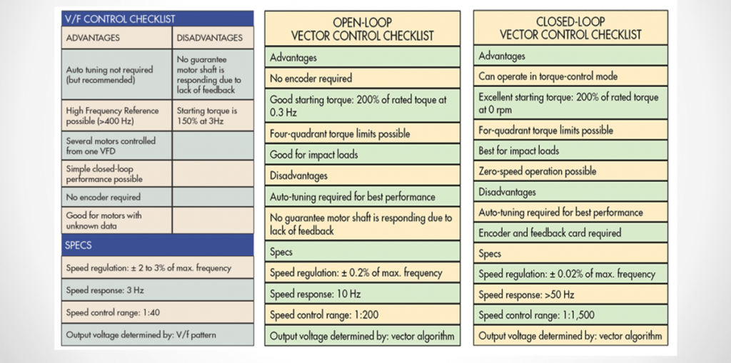
- AC Drive Control Mode Comparison
AC Drive Control Mode Comparison
Braking Methods
Once you have determined how best to control your motor when it’s running you must address the next big issue… how to stop the motor in a controlled manner. The following methods are most common.
Coast to Stop
- Uses a long deceleration time and simply lets the load coast to a stop. Simple and effective if you have the time.
DC Injection Braking
- Used to final stop high inertia loads.
Dynamic Braking
- Uses Resistor(s) to absorb excess energy from regeneration.
High Slip Braking – V/f Control
- Drive reduces output frequency in large steps, producing a high slip.
- Regen energy is dissipated in the motor windings.
- Duty cycle less than 5% because of motor heating.
- Do not use with Dynamic Braking.
Overexcitation Deceleration – V/f and Open Loop Vector
- Increase flux during deceleration to allow shorter deceleration time settings.
- Regen energy is dissipated in the motor windings.
- Do not use with Dynamic Braking.
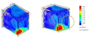
Why Do You Need Braking Resistors?
If there is more inertia than friction to slow the motor at the deceleration rate, then regenerative energy will be generated by the motor which causes the DC bus voltage to rise. Dynamic braking transistors will pulse on to bleed off excess energy through the Dynamic Braking Resistor (DBR). Braking resistor values must exceed the minimum ohms requirement for the drive or the drive will be damaged or destroyed due to excess current through the dynamic braking transistors. Duty cycle is critical. Higher duty cycles require that the resistor wattage ratings are sufficient to handle the heating generating from constant starting and stopping of the drive.
How Fast Can I Stop My Motor?
By using dynamic braking you can stop your motor in a relatively short period of time. But to understand how much time this will take you will need to run calculations based on the motor inertia, bus voltage of the drive, and the ohmic value of the dynamic braking resistor. An example of these calculations is below.
Max Deceleration Rate
- Power (Watts) = Energy (Joules)/t (Seconds)
- Energy (Joules) = ½ I ω2 (I=inertia, ω=angular vel.)
- Units are kg-m2/s2
- Need to include the inertia of the motor rotor.
- E.g. For total inertia of 0.0125 kg-m2 at 30,000RPM, energy = 61,685J .
- For the drive, use Ohm’s Law V=IR to calculate energy through resistor.
- E.g. for 240V drive, DC bus voltage is 340V. For 7.5HP drive, min resistance is 16 ohms (from catalog). Using Ohm’s Law, 340=16*I, or I = 21.25 Amps. Power = V*I = 340*21.25 = 7225 W.
- 61,685J/7225W = 8.54s
Line Reactors: Why You Need Them, Where & When To Use Them
Input Line Reactors
On the input side of the drive, they are used to reduce harmonics caused by the transition switching of the input diodes for the DC bus.
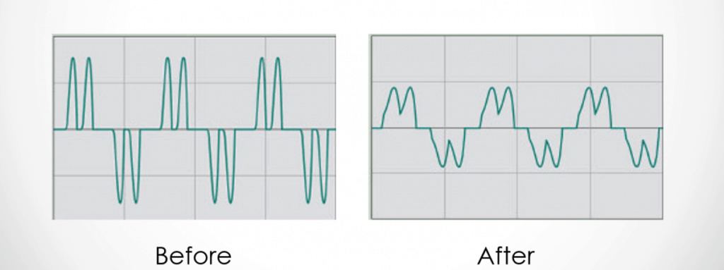
Output Line Reactors
On the output side of the drives, they have multiple uses. They can reduce voltage spikes caused by transmission line reflections in the motor power cable when there are long motor lead lengths, generally greater than 100’. They add inductance to the output when using a very low inductance motor as well as reduce motor heating due to current harmonics and reduce motor noise.
Output Frequency Matters!
Line reactor selection is dependent on the running frequency of the drive, so ‘3%’ and ‘5%’ numbers are referenced to 60Hz. Other frequencies will be different ratings.
Inductive Reactance RL = 2πƒL
- E.g. 7.5HP 240VAC drive operating at 500Hz;
- Output = 25A; for a 5% reactance .05 * 240 = 12V; by Ohm’s Law RL = 12V/25A = 0.48Ω; reactor L = 0.48/(2π*500) = 153μH
- For a 5% reactance at 60Hz, L=0.48/(2π*60) = 1.27mH. If you use that inductor at 500Hz, voltage drop will be 100V, which is a 42% reactance!