David Yoset | March 27th, 2017
When choosing a control system for your facility, there are many factors to take into consideration including system reliability (translated into plant uptime), upkeep and maintenance costs, installation costs, compatibility with installed control systems, quality of support from manufacturers, etc. But what about process safety? When is it necessary to choose a Safety Instrumented System (SIS) instead of a Basic Process Control System (BPCS)? And what do these two terms mean? In this article, we explore these questions.
Differences Between a SIS and a BPCS
ProcessOperations.com very clearly defines these two systems as follows:
“Process control systems (PCS) are active, or dynamic. They have analog inputs and analog outputs, perform math and number crunching, and have feedback loops. Process controls act positively to maintain or change process conditions. They are there to help obtain bestperformance from the process and often are used to push the performance to the limits that can safely be achieved. Hence, most failures in these systems are inherently self-revealing. PCS must be flexible enough to allow frequent changes. Process parameters (e.g. set points, PID settings, MAN/AUTO, etc) require changing. Portions of the system may also be placed in bypass, and the process may be controlled manually. They are not built with safety in mind and are not dedicated to the task. Because they are operating at all times they are not expected to have diagnostic routines searching for faults.
Safety systems, however, are just the opposite of process control systems. They are dormant, or passive. They sit there doing nothing and hopefully will never be called into action. An example would be a pressure relief valve. Normally the valve is closed. It only opens when the pressure reaches the set value. If the pressure never exceeds that value, the valve never operates. Many failures in these systems may not be self-revealing. If the relief valve is plugged, there is no immediate indication. A PLC could be hung up in an endless loop. Without a watchdog timer, the system would not be able to recognize the problem. There is a need for extensive diagnostics in dormant, passive safety-related systems. Safety systems should be incorruptible – need to be kept to a fixed set of rules and access for changes carefully restricted. And they must be highly reliable and be able to respond instantly when a hazardous situation develops.”
A common question people ask is, “Can I program a BPCS to perform safety functions?” The answer is absolutely “yes.”
But try to ask a BPCS manufacturer the following question: “Assuming that I write perfect bug-free code, can you guarantee with measurable certainty that your control system will consistently perform my safety functions on demand?” The answer you will likely receive is, “No.”
A key difference between process and safety control is the fact that you need to know, with measurable certainty, that the safety system will respond when required to. So, while you can program safety functions in a basic process control system, there is no guarantee that the system will do its job when required.
Real World Application Example
For those who are skeptical about a control system not doing its job when required, I offer the following personal real world example. I was in charge of designing, building, programming, and starting up a simple PLC control system for a wood-fired boiler in a lumber mill. After going through loop checks and commissioning, it was time to light a fire in the balanced-draft furnace and to bring the new PLC online.
In a typical balanced draft system, an Induced Draft fan and a Forced Draft fan act in tandem to keep the furnace under a slight vacuum. This way, if the furnace is not perfectly sealed, the combustion process remains in the furnace rather than affecting the environment outside the furnace. After several smooth hours of run time, it was evident that the brick furnace was not perfectly sealed because sparks and smoke began to puff through various small openings where brick met steel.
After a few panicked minutes of trying to pinpoint an issue with the PLC code, I realized that all of the I/O signals were static – nothing was changing. My PLC was locked up. The only solution was to toggle the power to the CPU. Once I did this, I was able to restart the fans and re-engage the draft control. I never saw this issue again on that job site, but I had learned that PLCs can indeed lock up. Thankfully my story does not include anyone getting hurt or injured unless you count my embarrassment of having a boiler house that smelled like a campfire!
With the basic differences understood, we can now explore one method of determining when to use a SIS based on the Safety Life Cycle.
SIS and SIL
Deciding whether to use a SIS is a subset of assigning Safety Integrity Levels (SIL). For more on SIL, please read my previous blog on the topic.
Safety Life Cycle
The Safety Life Cycle comes from two voluntary standards used by plant owners/operators to quantify safety performance requirements for hazardous operations:
- IEC 61508: Functional Safety of Electrical/Electronic/Programmable Electronic Safety-Related Systems
- IEC 61511: Safety Instrumented Systems for the Process Industry Sector
The Safety Life Cycle (see Figure 1) provides a repeatable framework whereby all process hazards are identified and analyzed to understand which hazards require the use of a SIS for mitigation. By design, this is a cyclic process, not a linear process with an endpoint. Any changes in process design, operating conditions, or equipment requires cycling back to the beginning to ensure any changes are properly implemented.
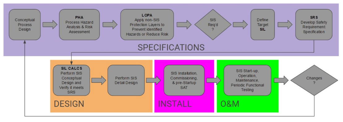
For the remainder of this article, we will focus on the steps to follow to determine when a SIS is required, starting with the Process Hazard Analysis.
Process Hazard Analysis
A Process Hazard Analysis (PHA) is a systematic assessment of all potential hazards associated with an industrial process. It is necessary to analyze all potential causes and consequences of:
- Fires
- Explosions
- Releases of toxic, hazardous, or flammable materials
- Etc
Focus on anything that might impact the process including:
- Equipment failures
- Instrumentation failures or calibration issues
- Loss of utilities (power, cooling water, instrument air, etc.)
- Human errors or actions
- External factors such as storms or earthquakes
- Etc
Both the Frequency and Severity of each process hazard must be analyzed:
- How often could it happen? Tank spills could happen any time there’s a manual fill operation (multiple times a year)
- How severe is the result? Localized damage, fire, explosion, toxic gas release, death
Core to the PHA analysis is the fact that things can and do go wrong. You have to forget IF it will happen and instead consider WHEN it will happen. Each identified hazard is assigned an “acceptable” frequency. For purposes of the PHA, you cannot assume a hazard will “never” happen.
- A hazard which results in simple First Aid could be considered “acceptable” if it could happen only once a year
- An explosion and fire due to a tank rupture could have an “acceptable” frequency of once in 10,000 years
The end result of the Process Hazard Analysis is a list of all possible process hazards with each one assigned an acceptable frequency of occurrence. With the PHA complete, the next step in the Safety Life Cycle is the Layer of Protection Analysis.
Layer of Protection Analysis
No single safety measure alone can eliminate risk. For this reason, an effective safety system must consist of protective layers. This way if one protection layer fails, successive layers will take the process to a safe state. As the number of protection layers and their reliabilities increase, the safety of the overall process increases. Figure 2 provides a generalized view of various protection layers. It is important to understand that each layer must function independently from the others in case one or more layers fails.
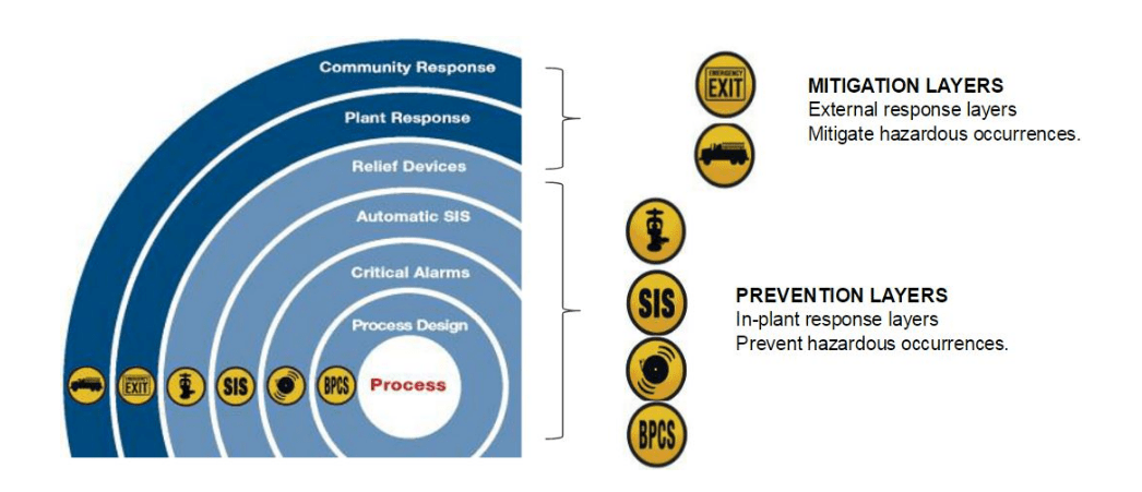
Some specific examples of Protection Layers include:
- Fire suppression systems
- Leak containment systems (dikes or double walls)
- Pressure relief valves
- Gas detection/warning systems
The general steps of a LOPA are as follows. For every Process Hazard identified in the PHA:
- List all available non-SIS safety measures
- Assign each layer its own hazard risk reduction factor
- Calculate an effective hazard frequency with protection layers applied
Example: A tank fill operation that happens 250 times per year – “could” experience an overfill event 250 times per year.
- A protection layer in the form of a proper vent/drain system could reduce the danger by a factor of 100 (risk reduction factor)
- The hazard resulting from tank overfill would have an effective frequency of 250/100 = 2.5 times per year
After the effective hazard frequency of each hazard is known, the key question is: “With non-SIS protection layers applied, is the effective frequency lower than the acceptable frequency?”
In other words, once all Process Hazards are identified, and Protection Layers assigned if the PHA/LOPA study concludes that existing protection cannot reduce risk to an acceptable or tolerable level, a Safety Instrumented System will be required.
For those hazards where existing protection layers (including the BPCS) can reduce risk below the acceptable level, a SIS is not required and it is acceptable to use the BPCS for hazard mitigation.
Safety Instrumented Systems and Functions
The purpose of a SIS is to take a process to a “safe state” when predetermined set points have been exceeded or when safe operating conditions have been transgressed.
The role of the SIS is to reduce risk by implementing Safety Instrumented Functions (SIF). Two example SIFs include:
- Hazard: Tank overfill. SIF: The SIS stops the fill pumps at a predetermined safe level
- Hazard: High temperature. SIF: The SIS opens a relay to cut power to a heater circuit at a predetermined safe temperature
In any case, an SIF is a safety function implemented by the SIS to achieve or maintain a safe state. An SIF’s sensors, logic solver, and final elements act in concert to detect a hazard and bring the process to a safe state.