This technical guide details how to use an Omron OS32C Safety Laser Scanner with a Universal Robot. You can see how the two work together in our video demo.
We’ll explain the OS32C configuration software and setup, as well as how to physically connect the scanner to the robot. In addition our guide will specifically show how to set up a Safety Zone for robot protective stop, and a Warning Zone for robot reduced mode. This guide is a simple example, and will not detail all setup options for the scanner or the robot.
Once the OS32C is powered and connected to the configuration software on the PC, the desired Safety and Warning Zones, along with the appropriate output parameters, need to be set.
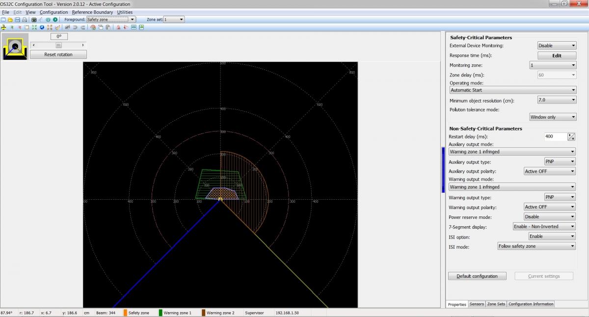
Upon initial connection, the Configuration Software window should look like the picture here (Figure 1.1). If this is the first time the scanner has been powered on, it may have a default Safety/Warning Zone configuration and will not look exactly like the zones shown here. In this note, we’ll configure one Safety Zone, one Warning Zone, and will ignore Warning Zone two.
Figure 1.1 (Click to Enlarge)
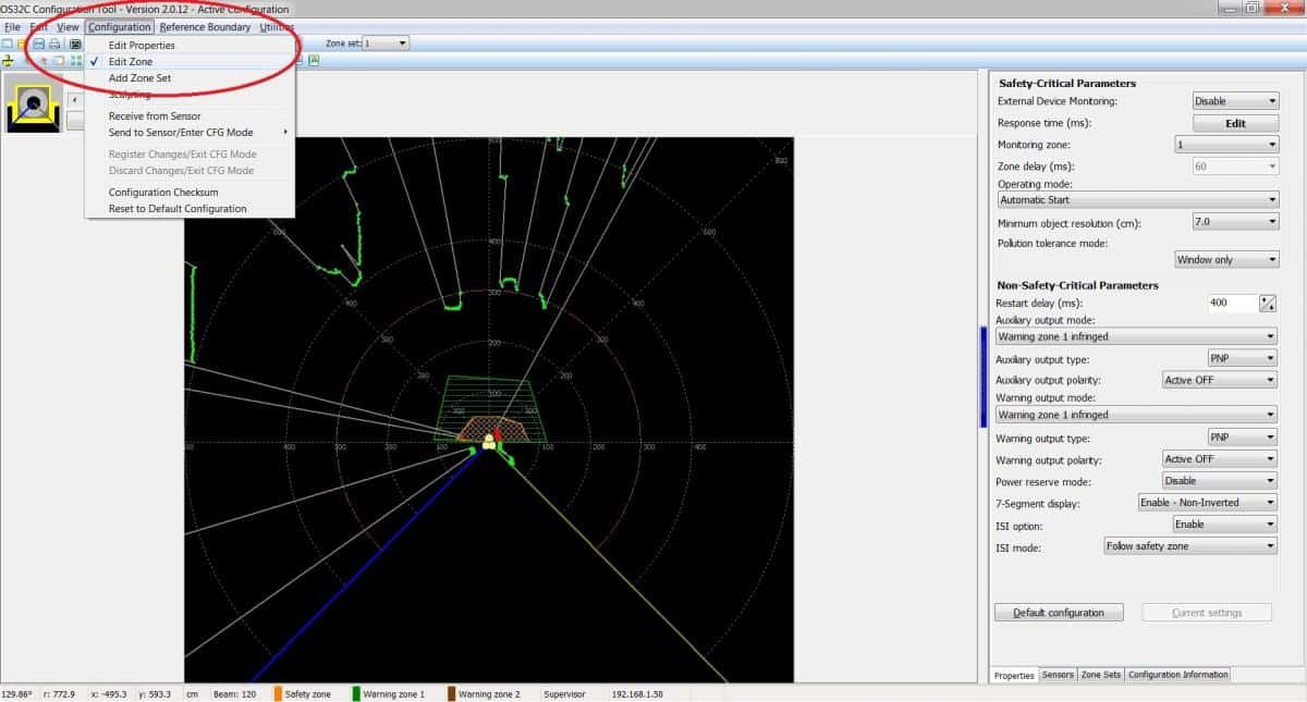
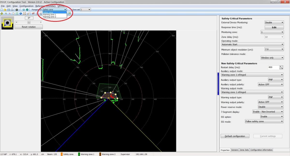
In the upper left of the configuration software, select “Configuration -> Edit Zone.” Then select the Safety Zone as the foreground selection. (See pictures below).
Figure 1.2 (Click to Enlarge)
Figure 1.3 (Click to Enlarge)
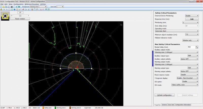
The Safety Zone is now highlighted and has “click and drag” circle elements (see figure 1.3). Next, sculpt the Safety Zone into the desired size and shape for the application.
Repeat the above steps for the Warning Zone (see pictures 1.2 and 1.3 above for reference). In this example, the Safety Zone is set up as a half circle with a radius of 1 meter and the Warning Zone is a half circle with radius 2 meters.
Note: The lines with green and red dots show a snapshot of what the scanner “sees” in its environment. To actively monitor, select “Utilities -> System Monitoring” to get an idea of the surroundings and what the size of the zones should be.
Figure 1.4 (Click to Enlarge)
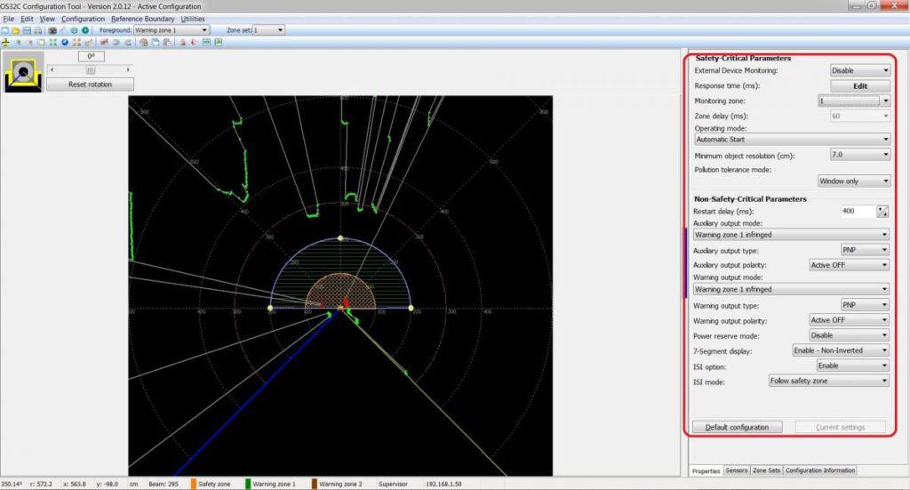
The section here on the right of the configuration window (figure 1.5) shows the safety parameters, along with non-safety parameters that dictate the behavior of the OS32C.
Note that the “Operating Mode” is set to “Automatic Start.” This will ensure that the scanner begins monitoring the zones and performing as programmed upon power up of the system.
In the Non Safety-Critical Parameters, the Auxiliary output and the Warning output are of special interest for this setup. Ensure that the following are set correctly:
Figure 1.5 (Click to Enlarge)
The above selections will ensure that when an object or person enters the warning zone the robot will enter reduced mode. Save the configuration and select “Configuration -> Sent to sensor/Enter CFG mode -> Entire Configuration. Confirm all settings and select “Yes” to register changes. The scanner will reboot and the configuration will now be active.
This example uses the Universal Robot to provide power to the OS32C.
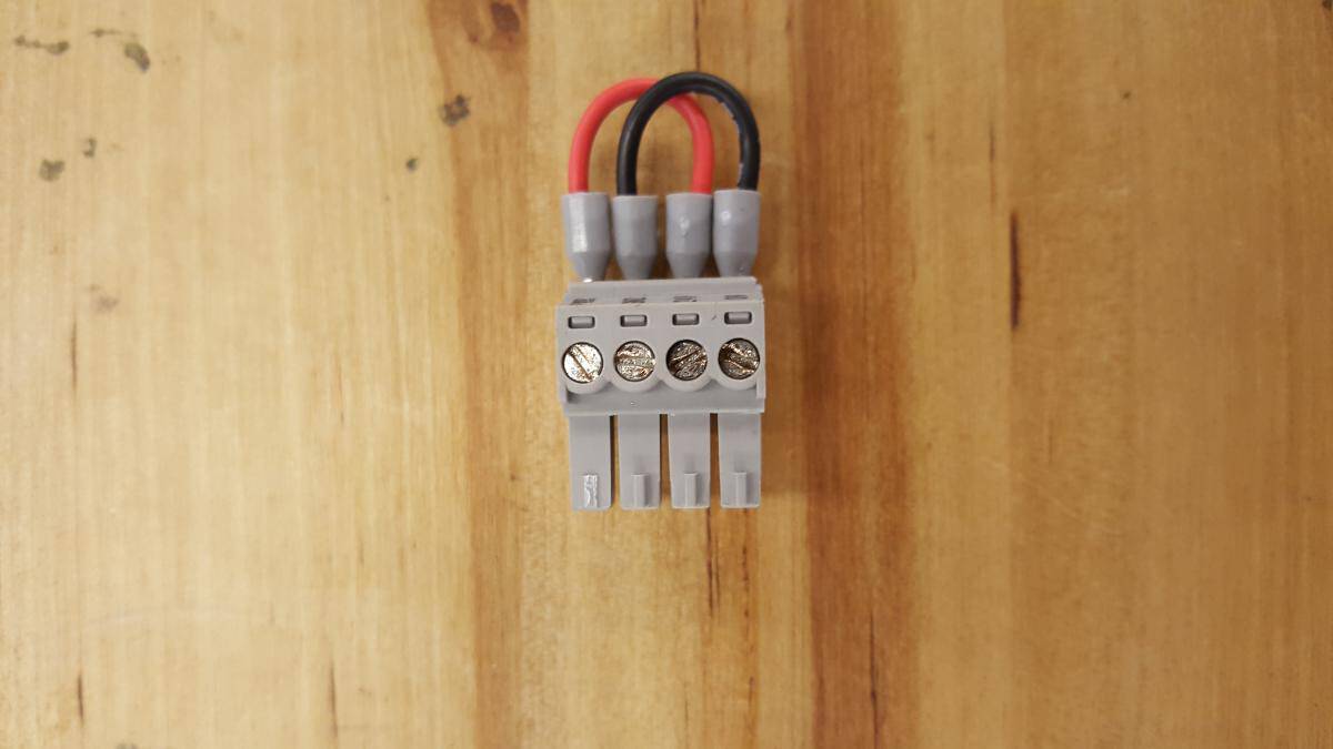
To connect power to the OS32C, use the connector in the Universal Robot Controller that contains the red and black jumper wires. (Figure 2.1)
Figure 2.1 (Click to Enlarge)
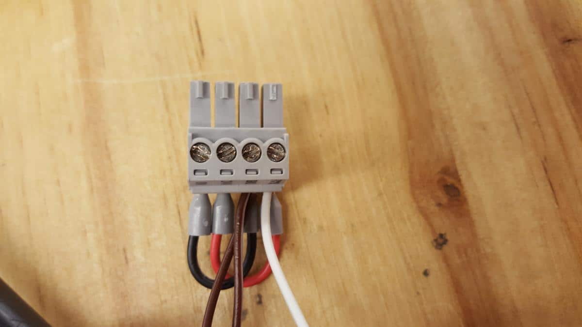
Next, wire the 24 V and 0 V connections of the OS32C into the “PWR” and “GND” terminals respectively. Also, when not using the External Device Monitoring function, that wire also needs to be connected to GND:
Figure 2.2 (Click to Enlarge)
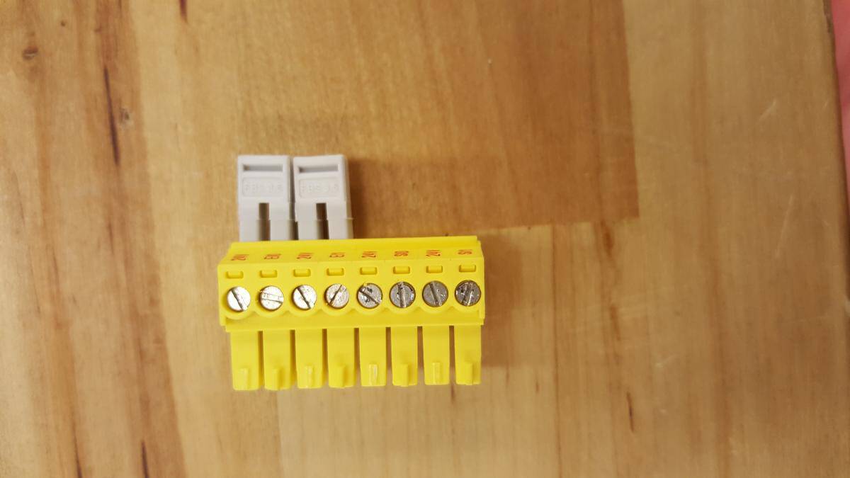
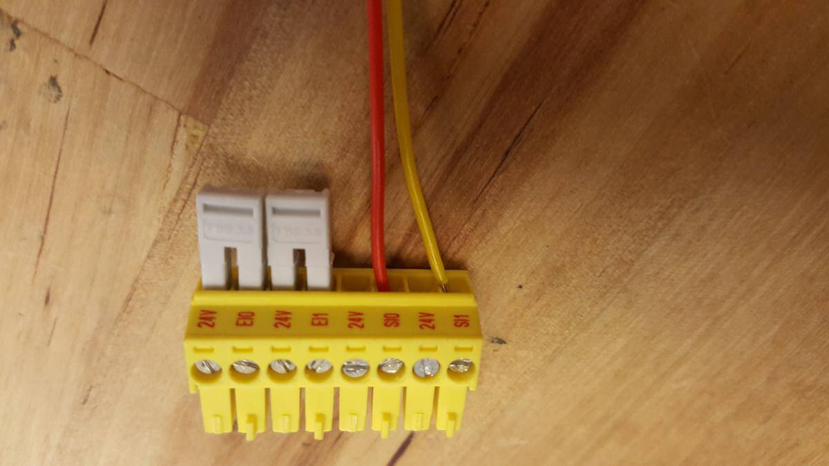
Next take the Safety I/O Terminal (with the plastic terminals) and remove the jumpers from the bottom two terminals (SI0 and SI1):
Figure 2.3 (Click to Enlarge)
Wire the two Safety Outputs (OSSDs) of the scanner into SI0 and SI1 (Red and Yellow wires):
Figure 2.4 (Click to Enlarge)
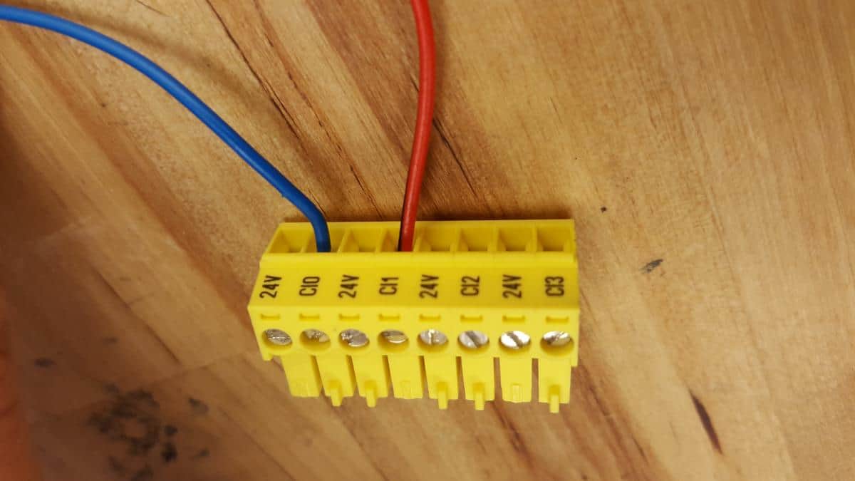
Now use the Configurable Input connector (CI0 – CI3) and wire the Warning and Auxiliary Outputs (Blue and Orange/Black wires) of the scanner into CI0 and CI1:
Figure 2.5 (Click to Enlarge)
Plug all connectors back into the appropriate terminals in the robot controller, and power on the robot.
The scanner should boot when the robot reaches the Initialization Screen. Initialize the robot as outlined in the user manual.
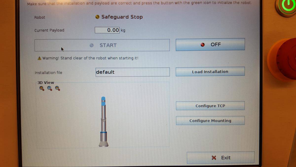
If you press the “On” button, and the Safety Zone of the scanner is infringed or it has not completed booting, the robot will not be able to be fully initialized and you will see the following:
Figure 2.6 (Click to Enlarge)
Once the scanner has booted and there are no Safety Zone infringements, Initialization can be completed.
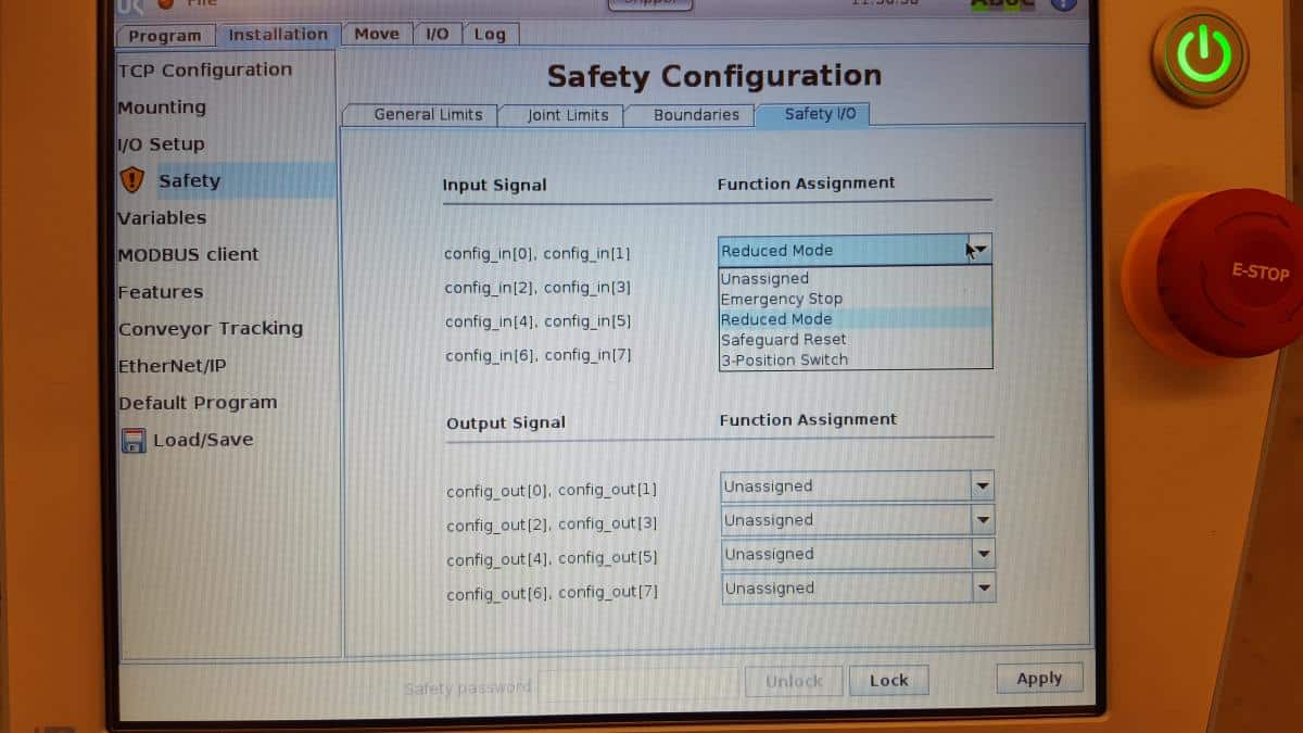
Next, navigate to the Safety I/O Setup screen. From the home screen press: Program Robot -> Installation Tab -> Safety (Enter correct password) -> Safety I/O Tab.
Select Configurable inputs 0 and 1 for reduced mode:
Figure 2.7 (Click to Enlarge)
Press “Apply” and accept the restart to apply the new safety settings.
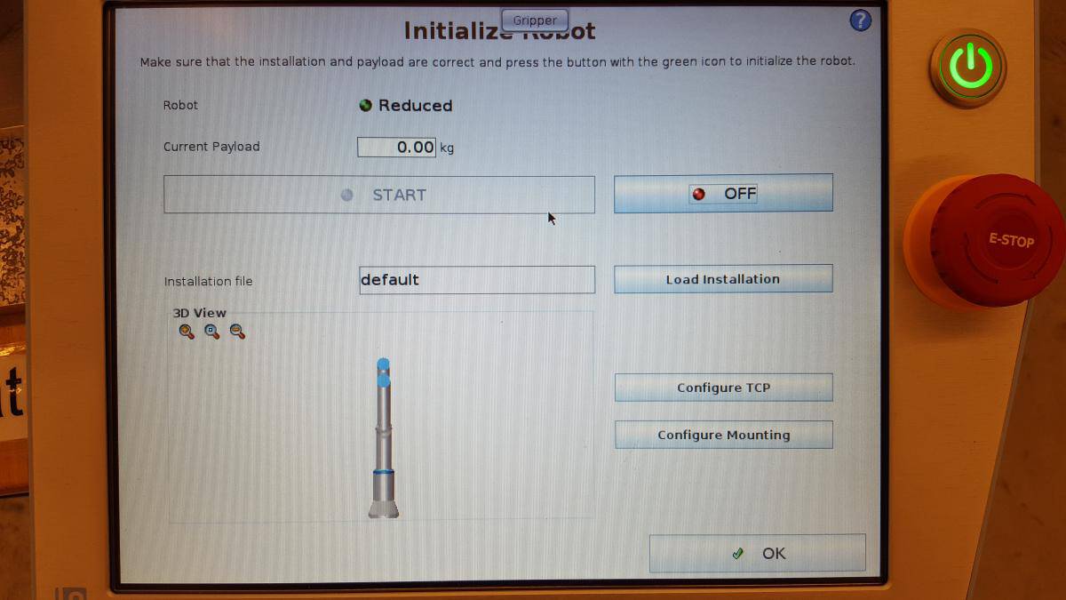
At the Initialization screen, test the reduced mode function by entering the Warning Zone. If working properly, the robot status indicator will say “Reduced:”
Figure 2.8 (Click to Enlarge)
Now the robot can be programmed (or a program can be run) and the Safety settings will apply.
If the Warning Zone is infringed, the robot will enter reduced mode and perform at the reduced mode settings entered in the Safety setup. Note that you will not be able to alter the reduced mode settings until a set of configurable inputs are set for reduced mode.
If the Safety Zone is infringed, the robot will enter a protective stop mode, and if a program is running it will pause. In this setup, the robot will continue automatically when the Safety zone is clear.
For more information about the Omron OS32C safety scanner and implementing with Universal Robots, reach out to one of our robotics experts. Our team can work with you to ensure your equipment is set up to keep your operation running safely and efficiently.
"*" indicates required fields
We’re looking through thousands of pages to find the most relevant information.
In the meantime, enjoy these fun facts…