Barry Meade | November 10th, 2016
Most of us have seen a clean, well-organized control panel out on the factory floor – you know it when you see it! Conversely, you also know a poorly designed panel when you see it – not well laid out, crowded, messy, wires hanging all over the place, etc.
Whereas neatness is probably the first thing that jumps out about a well-designed panel, neatness is really the by-product several other well-executed aspects of panel design.Four of the main aspects of panel design are discussed in this article:
- Layout and Component Placement
- Labeling
- Panel Sizing and Component Spacing
- Wireway design
Layout and Component Placement
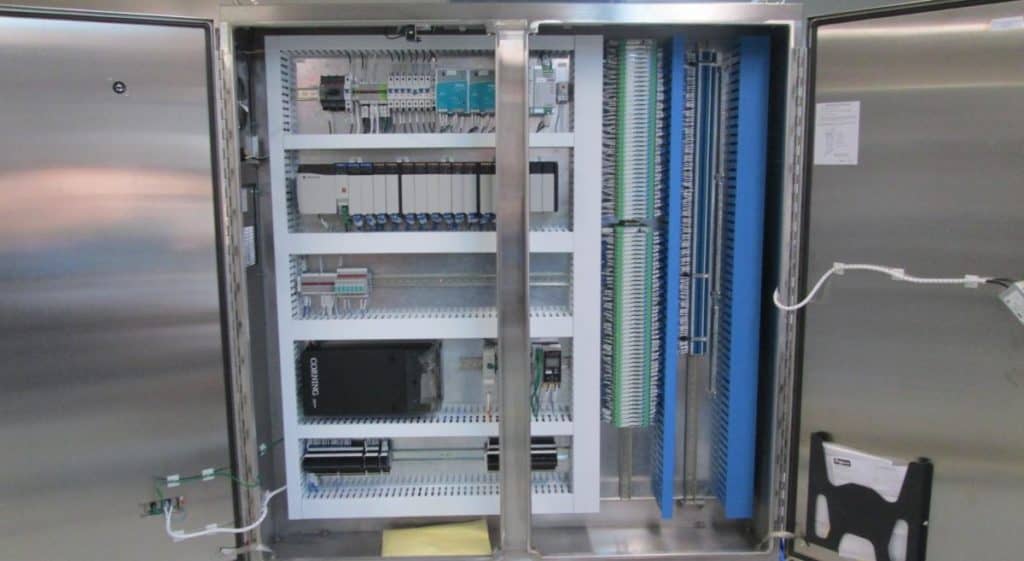
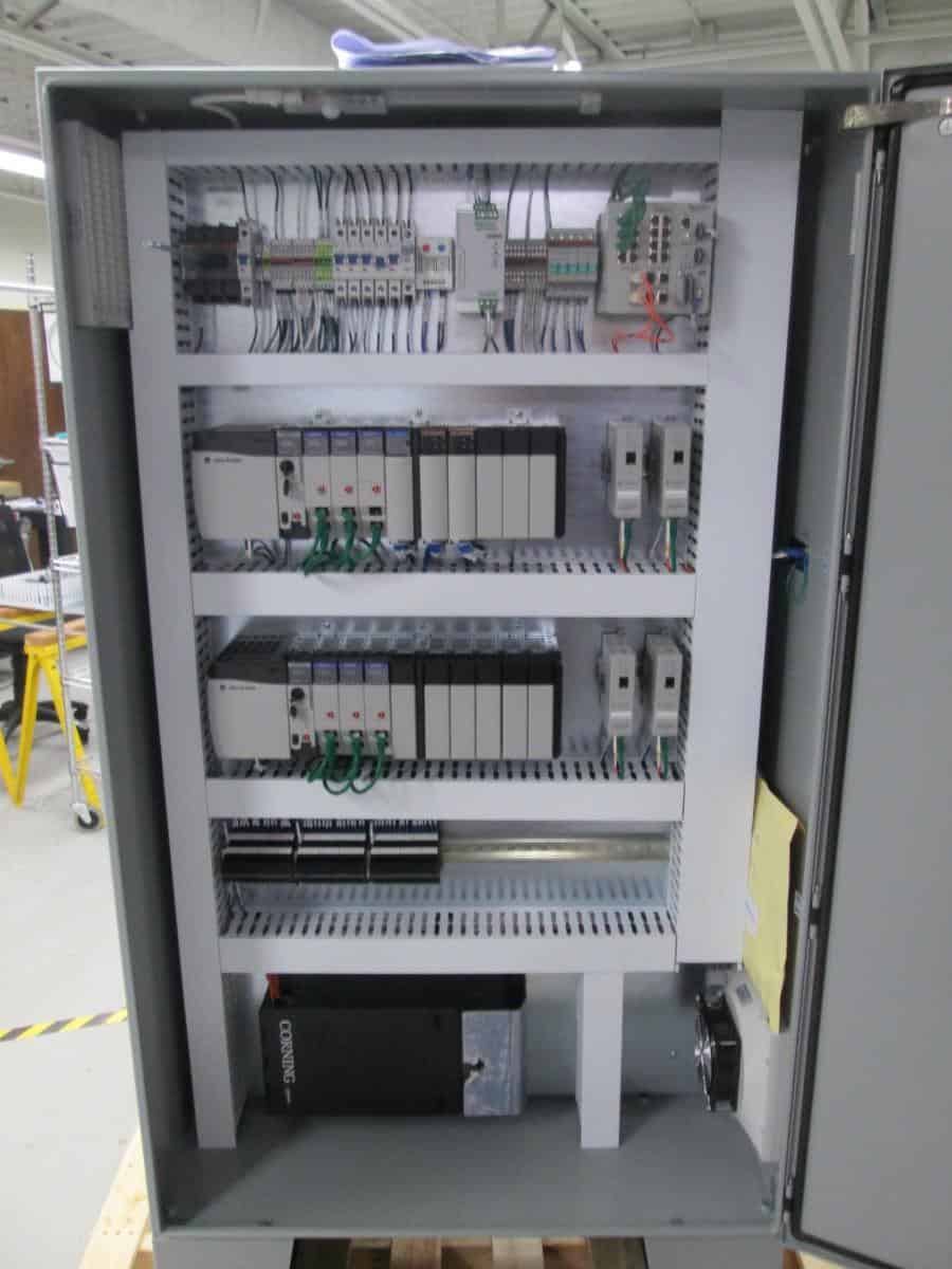
In any control panel, components or “component groups” must be laid out in a logical-functional manner. Since most panels have a main incoming power disconnect switch, most commonly located in the upper right of the panel, it makes both logical and functional sense to locate the components with the highest voltage rating at the top of the panel. From there, the power distribution down to the power components at the lowest voltage level (most commonly 24VDC) should generally follow a left-right and top-bottom hierarchy.
Each group of power distribution components should start with a main breaker for that power level at the left, followed by distribution breakers, fuses, and terminals. This keeps each power distribution group consistent and functionally sound, and facilitates easy troubleshooting in conjunction with a good design package that reflects this hierarchy in the schematics (another topic for another day). Enough space should be left between these groups to allow for ease of expansion. This is easily achievable when the control panel is sized appropriately for the application wherein it will be used.
The PLC racks and I/O terminals are typically placed below the power distribution components. This is good practice from a couple of standpoints. For one, since heat rises, it makes sense to place sensitive electronic equipment (such as a PLC) below the hotter power components at the top. A well-designed panel will incorporate the means for expelling the excess heat at the top of the enclosure. Secondly, field instrument I/O wiring is usually brought in from the bottom of the panel. When I/O terminals are located at the bottom of the panel, this makes it very easy to land the field wiring.
Labeling
The value of proper labeling within the control panel cannot be understated! Not only should every component in the panel be labeled, but the syntax on the labels must make sense, and the labels should be placed such that each one is clearly visible.
For wiring, labels must be applied at each end of the wire. For power distribution wiring that connects to a power distribution terminal, the wire is labeled per the terminal number. For all other power distribution wiring and for “general” wiring (i.e. – non-PLC I/O wiring), the wire is labeled per the corresponding line number in the schematics. For PLC I/O wiring (i.e. – wiring that connects to a PLC input or output), each wire should be labeled per syntax that corresponds with its PLC address.
For panel components (i.e. – power supplies, breakers, etc.), the component is typically labeled with a standard abbreviated prefix identifying the type of component, followed by the corresponding line number for that component in the schematics.
For Terminal Bank labeling, the Terminal Bank header identifier prefix usually starts with “TB”, followed by a 2-5 character identifier identifying the function (e.g. – “DI” for digital inputs; “AC120” for 120VAC power distribution). This is then followed by a numeric value (usually starting with “1”) which increments with each successive terminal group within that function. For the individual terminals, numbering usually starts with “1” for each group within the function.
When wiring and components are labeled in this manner, it makes it easy for troubleshooting, because it’s easy to identify them in the schematics as well.
Panel Sizing and Component Spacing
For a well-designed control panel, the panel is sized to allow for “generous” component placement (i.e. – allows for plenty of room between components, both horizontally and vertically). Adequate horizontal room will give space for addition/expansion for components such as power distribution breakers and terminals, PLC racks, I/O terminals, etc. – and will also allow for proper heat dissipation for power components. Adequate vertical room will give much needed space to land wiring into terminals neatly – and thus avoid crowding. Adequate vertical space will also allow power components to dissipate heat properly. In addition, plenty of room should be left at the bottom of the control panel to allow for coiling up spare field wiring.
Wireway Design
The last item in this discussion is wireway design. A good control panel design incorporates the right type and the right amount of wireway. The whole purpose here is to give plenty of room for both internal panel wiring and for field I/O wiring to be routed to the I/O terminals.
Wireway must be designed to allow ease of termination of internal wiring to internal panel components. As mentioned earlier, enough space should be given so that the wiring can be brought neatly to each panel component, and such that the wire labels are clearly legible. Also, the wireway must be sized properly to allow for future wiring additions when components are added to the panel.
Wireway that will convey field I/O wiring to its respective I/O terminals must be generously sized to meet the assumption that field wiring will be brought in and terminated into every existing I/O terminal. In addition, the sizing should account for additional potential I/O wiring in the future if components are added to the panel.
In conclusion, when it comes to producing a great control panel, these four primary aspects cannot be overlooked. Adhering to these guidelines will not only produce a great looking and organized panel, but it will also produce a highly versatile panel that is capable of expansion and is also easy to troubleshoot when problems arise.