When creating or expanding your Siemens PCS 7 project, there are several bulk systems engineering tools available to assist in the process to optimize efficiency, organization, and future flexibility. In this article, we’ll cover:
These Siemens tools allow you to create templates used to generate several instances in a short amount of time and to efficiently edit large pieces of programming from a central interface. You may wonder how exactly these tools will benefit your application. By utilizing these tools, you are allowing yourself; consistency among control modules or sequences of the same type, efficient bulk creation, one-time approval of a type template, and bulk modifications of several instances at once.
The alternative to using these systems engineering tools is to manually create each and every control module and sequence. This method would undoubtedly require more engineering time while creating more room for error and a lack of consistency. While using these tools will take more upfront planning and consideration, it saves time in creating, testing, and modifying individual instances. The more familiar you become with these tools, the more you can recognize how to utilize them to their full potential and how the upfront planning and decisions result in optimal results with minimal engineering.
What are Process Tag Types?
A Process Tag Type is a logic chart that is configured for any control module type that will have multiple instances (e.g. valves, motors, PID controllers, analog monitoring). The Process Tag Type provides a standard template by which all similar control modules will follow.
These template charts are stored in and modified from the Master Data Library assigned to your PCS 7 project. You use a tool called Import-Export Assistant (IEA) to create these templates and import their instances into your project.
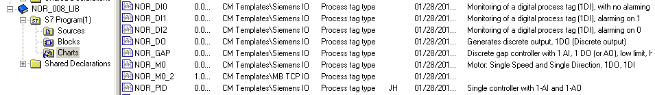
Figure 1: Project Master Data Library
Control modules such as valves, motors, and PID controllers, inherently have several similarities from one instance to another. It is important to recognize these similarities, and differences as well, to determine the templates you will need. For example, a set of valves may have dual feedback while another set may have no feedback at all, so you can create a type or template for each.
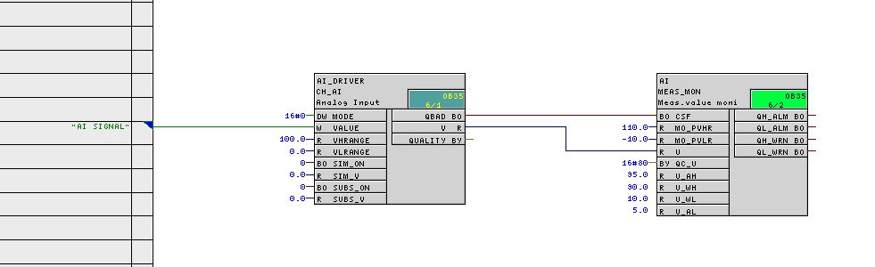
Figure 2: Example Process Tag Type for analog monitoring
A Process Tag Type chart is created for each template. You then identify any differences between the instances of the template by selecting certain parameters to be user defined and applied prior to instance creation. Examples include ranges, alarming, units, block comments, I/O signals, and its location in the project. These are the parameters and signals that will be available for population in a file called the “import file” or “IEA file” (import-export assistant file) which is used to generate all of the control module instances.
Creating Process Tag Types
First, you must identify, create, and test templates needed for the project. Testing is an important step to ensure that every instance created from the template functions as anticipated. Some examples include:
- Analog input with alarming
- Discrete input with alarming on closed limit
- Discrete input with no alarming
- Valve with dual feedback
- Valve with no feedback
- Motor
- VFD
- PID loop
Siemens provides sample Process Tag Type templates which can be used or modified to fit your specific needs. Cross Company has compiled our own library of Process Tag Types as well, with options that incorporate common requests for other features or functionality.
The next step is to create/modify the Process Tag Type. You select individual I/O points for “parameter” and “signal” which are flagged to be the user-defined parameters explained previously, to be defined for each instance.
- Parameter – alarm limits, ranges, monitoring time, PID parameters, etc.
- Signal – connectors for I/O signals assigned to the device (AI, AO, DI, DO).
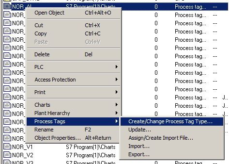
Figure 3: Selection to create/change Process Tag Type
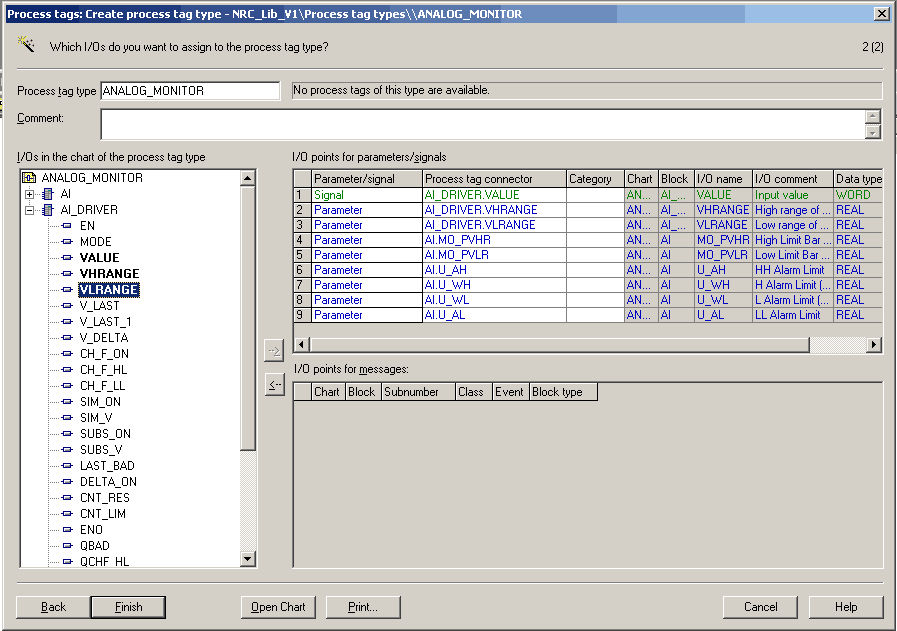
Figure 4: Selecting I/O as parameters and signals to be user-defined
Assign/Create Import File
Import-Export Assistant Files – referred to as “import files” or “IEA files” – are used to populate instance-specific information for each control module that you are creating from the same template. For each Process Tag Type, you create (or assign, if already existing) an import file that contains a column group for each user-defined parameter and signal for that Process Tag Type. Each row in this import file corresponds to an instance you are creating that is based on your template Process Tag Type.
For each instance, you define its location in the project (or “plant hierarchy”), its name, and its individual parameter and signal assignments. With enough pre-planning, you can also enter chart interconnections; e.g. connections to an area simulation chart for enabling/disabling simulation for that module.
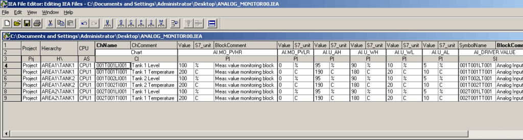
Figure 5: Snapshot of an import file with six analog monitoring instances
Importing Process Tags
Upon completing your IEA file, you can then run the Import command on your Process Tag Type to create those instances in your project. An instance that is created in the project from a Process Tag Type is called a process tag. Once imported, please note the following considerations:
- Do not change block names or Process Tag Type name – these will break the link to the Process Tag Type.
- You cannot add/remove blocks or change interconnections/parameters by changing just the Process Tag Type; this will require a re-import.
- To re-import, you can delete and import instances by running the IEA file with ‘import mode’ set to delete.
- Do not run a re-import after making connections to other charts; these connections will be lost.
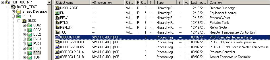
Figure 6: Project plant hierarchy containing imported process tags
What is Process Object View?
During system configuration and, subsequently, during process operation, the Process Object View offers the possibility of editing charts created via the IEA in tabular form.
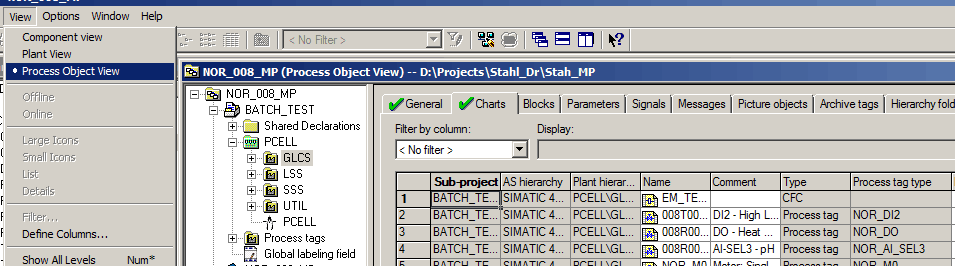
Figure 7: Selection to open Process Object View
In the Process Object View, you can edit attributes of individual process tags of the project. To make a change to all process tags of a certain process tag type, you can filter by Process tag type.
Editing Available in Process Object View
When selecting a hierarchy folder from the left plant hierarchy view, any charts in that folder and all folders below are displayed for editing.
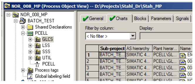
Figure 8: Charts in the “GLCS” area of the plant
This view displays all aspects of the process tag/object across several tabs. Examples include chart or block comments, parameter values, HMI block icon orientation, interconnections, value archiving settings, messages, etc. Jumps to CFC, SFC, HW Config & WinCC Explorer allow editing of aspects not available for editing in Process Object View.
Attributes are visible as long as they are defined as a “Parameter” or “Signal”. A white background identifies attributes available for editing. If the attribute you desire to change is not listed, this can be set to a parameter or signal by selecting the option in figure 9.
You may also notice that Figure 9 uses filters to narrow the view of data. This is just one of many features of Process Object View to optimize bulk editing of your system.
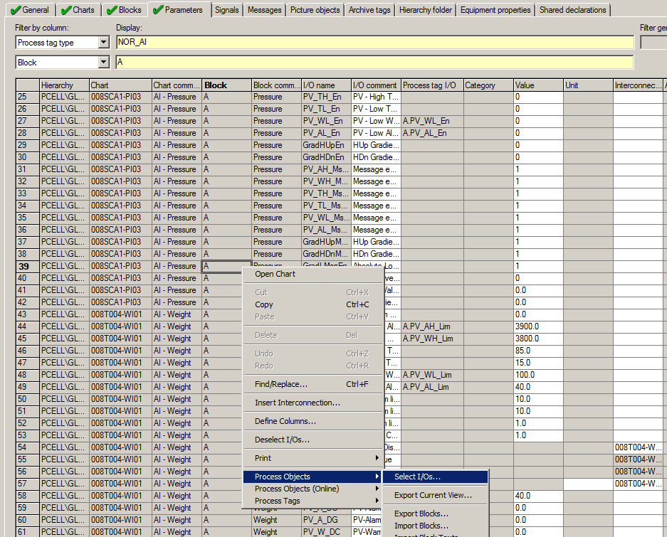
Figure 9: Selecting I/O to add to a filtered list of parameters in Process Object View
Process Object View Features
Features of Process Object View include:
- Filtering and sorting – this allows the user to narrow the focus of their bulk change (e.g. to a specific block or process tag type) or sort to view relevant data quicker.
- Import/export – this allows the user to export the contents of Process
- Object View to make edits in a 3rd party software and re-import the results (note: this function ignores any filters applied).
- Split view with display in two windows – this feature is present by dragging the scroll bar to split the screen in two and avoid constant scrolling left or right for ease of viewing and editing.
- Hide columns – this feature allows the user to reduce the amount of data shown in one view for ease of viewing and editing.
- Find and replace – this feature does as it states, allowing the user to find and replace specific values.
- Undo – this feature is uniquely useful in a PCS 7 project since the Undo function is not present in other logic editor tools (e.g. CFC editor or SFC editor).
The screenshot in Figure 10 demonstrates uses of a few of the features described above.
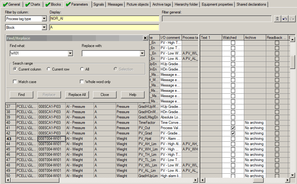
Figure 10: Utilization of Process Object View
What are Sequential Function Chart Types?
Sequential Function Chart Types (SFC Types) are like Process Tag Types for sequences. You create a template sequence that contains logic for a generic function that is repeated throughout a plant. The SFC Type is stored in your controller charts folder, like the continuous function charts (CFC charts), but are edited using the SFC Editor.
This template sequence is the SFC Type and the multiple areas, equipment, or process specific instances are deployed as blocks of code in your project. Each block instance is connected to its specific logic charts (devices, external code, etc.) to perform the sequence logic on its specific equipment or area.
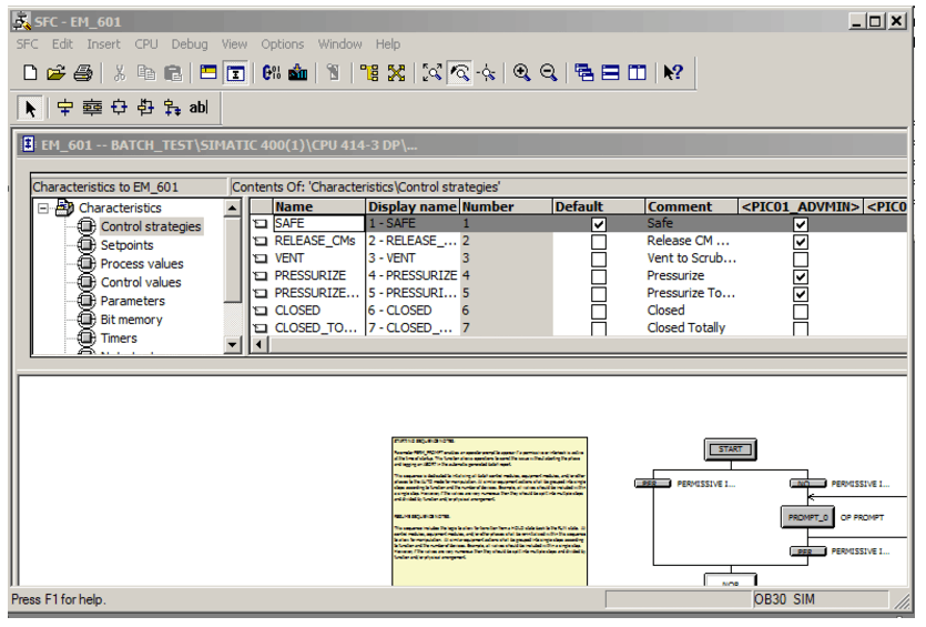
Figure 11: View of an SFC Type in the SFC Editor tool
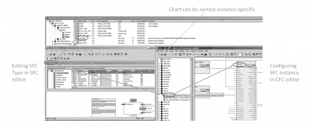
Figure 12: Overview of SFC Types and Instances
How To Identify Sequence Templates For a Plant
First, you must be aware of the standards that are available to take the guesswork out of designing your project. S88 Standards are the most widely adopted process control system configuration standards for manufacturing in the U.S. and Europe. Following these standards when planning your project allow you to design a flexible control system, and help you avoid common pitfalls or irregularities. These two blogs (linked above) provide a great detailed explanation of the background knowledge needed to design your Siemens PCS 7 project.
Second, once you understand how to follow the S88 Standards for your project design, you need to be able to recognize where you can apply these standards to allow for the bulk creation of sequence instances.
When designing and configuring sequences for your PCS 7 project, you have some flexibility and control over whether two process sequences can follow the same template. As long as two process sequences have the same pieces of equipment being controlled and follow the same general steps, a sequence template, or SFC Type, can be designed and maintained to be utilized in multiple instances.
It is important to keep things simple and general when designing SFC Types, to take advantage of several instances using the same sequence template. Common examples include:
- Agitator control
- Material loading/unloading
- Reactor temperature control
Configuration
SFC Types have a set of characteristics that are used when programming the sequential logic steps and transitions (actions and verifications).

Figure 13: List of characteristics for the SFC Type in the editor tool
These must be named in general terms to be applicable to every instance of the type. Some examples:
- Control strategy: FILL TANK.
- Setpoint: FILL_SP for setpoint to stop filling.
- Process value: TK_LEVEL to read tank level.
- Control value: TOT_STRT to start totalizer.
- Block contact: BTM_VALVE for a bottom valve.
An example logic step would command open BTM_VALVE and send a signal to TOT_STRT. The transition step would then wait for TK_LEVEL > FILL_SP until the next step would command the valve closed and stop the totalizer.
Cross Company has developed and maintains internal documentation to define standards to follow in configuring SFC Types. This allows for efficient and consistent engineering throughout projects.
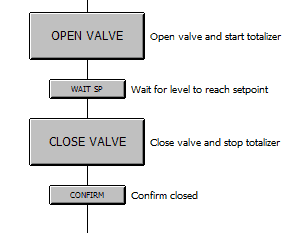
Figure 14: Sample logic in an SFC Type sequencer
Instances
SFC Types are organized in libraries and are handled as normal function blocks, i.e. laid in a CFC chart, parameterized, and with interconnections linked.
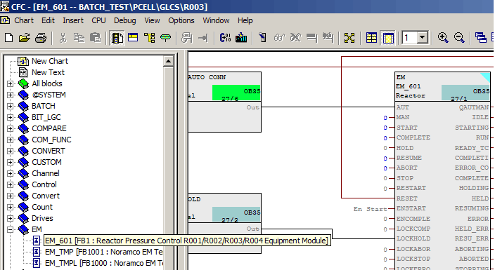
Figure 15: SFC Type used in an instance chart
Each general characteristic that was defined in the SFC Type is now connected to its instance-specific devices for monitoring and control. The diagram in Figure 16 shows the logical connections made for the “Fill Tank” example described previously.
Defined parameters which are evaluated in the sequence can have their values interconnected at the instance to use a unique value– denoted “Instance value” in the block properties.
Each instance generates its own HMI block icon for monitoring and control of that specific instance. A faceplate for each instance icon allows operators to control each sequence (Start, Hold, Resume, Abort, etc.) and to view the status of a running sequence, down to the specific step or transition being evaluated.
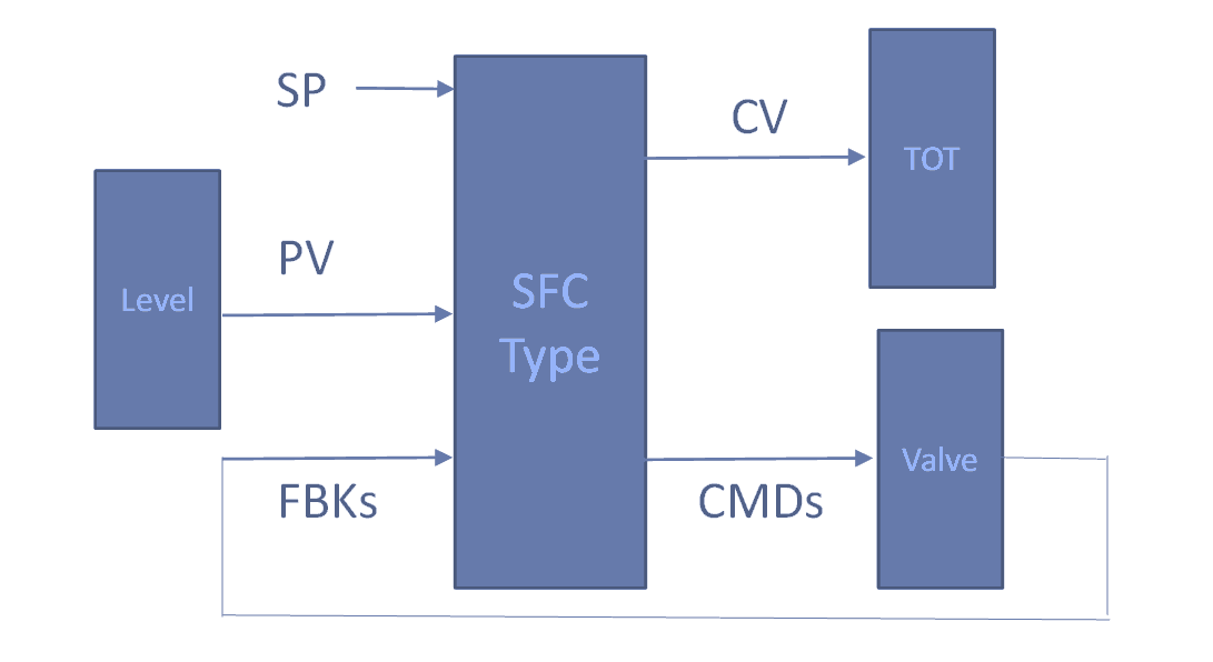
Figure 16: Logical connections of an SFC Type instance
Editing SFC Types
Making a change to the SFC Type in the SFC editor applies this change to all instances of that type. Common examples include adding another control strategy for additional equipment functions or adding a valve for redundancy in sequence operation. Also, just like Process Tag Types, since SFC Types are deployed as blocks, they can have certain attributes edited using Process Object View.
As a Siemens solution partner for automation drives, our team of experts have experience working with Siemens PCS 7 in a range of applications and can help ensure your operation is running efficiently. Contact an expert today to discuss your application!