As a mobile machine integrator for the past fifty years, we’re very familiar with the idea of “ if it isn’t broken, don’t fix it,” meaning that if the design of a machine is good enough, there is no need to improve. This is the case for hydraulic reservoirs, where many companies are still using legacy designs. A common rule of thumb when it came to sizing was 2:1, twice the amount of flow, to allow for dwell time and de-aeration. With the focus on having enough fluid capacity, efficiency wasn’t a primary concern, resulting in tanks that were frequently bigger and heavier than they needed to be.
OEMs today, however, are under extreme pressure to produce machines which are more efficient to manufacture and more efficient to run. And the size of the hydraulic reservoir is one area which is frequently overlooked but can yield significant savings. Cross partner Schroeder Industries has invested in simulation software and CFD analyses to provide data on tank dynamics and characteristics to uncover inefficiencies in the tank assembly.
Using this data, Cross works with our customers to optimize their reservoir size and design which can reduce the size of the tank needed. A smaller tank leads to:
- Improved machine energy efficiency due to overall weight reduction and reducing the warm up time needed
- Reduced oil consumption over the lifetime of the machine, from initial fill to repeated customer use
- Reduced initial manufacturing cost by using a tank with less material
- Increased space on the machine which can be used for either new/improved components or for increased payload
- Improved pump inlet conditions by reducing aeration and turbulence
Reservoir analysis looks at four areas:
- Volume optimization: Identifies dead zones where fluid stagnates and is not effectively used by the system
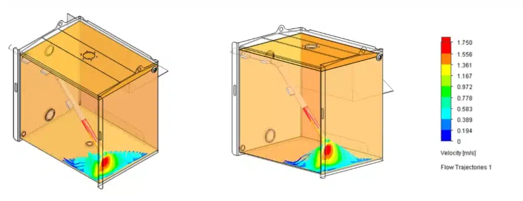
- Fluid velocity: A lower fluid velocity helps keep oil de-aerated and prevents new air from entering the fluid due to sloshing and turbulence.
- Temperature: Mapping can show how quickly and evenly the fluid reaches operating temperature and identifies hot spots which could lead to fluid degradation
- Structural: Not only do we examine how the fluid circulates, but we look at whether the reservoir will deflect or fail when full or be damaged when mounted or load bearing.
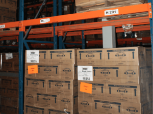
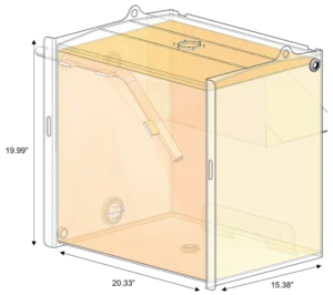
Below is a recent example of analysis that Schroeder and Cross did for a Cross customer manufacturing utility trailers. Their existing reservoir uses Mobile Fluid 424 at a nominal operating temperature of 70℉ with a volume of 24.44 gallons, a 0.56 gallon drawdown.
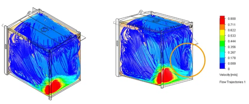
The turbulence created by the downpipe can be seen in the red circular areas above and below. This returning flow could be handled in a way that maintains significantly smoother and more laminar flow paths. This is the ultimate goal of tank optimization – to minimize turbulence and abrupt changes in flow paths.
 Schroeder also tested both surface velocities and de-aeration performance and both were found to be within acceptable limits.
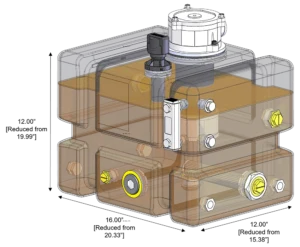
With all this data in hand, the recommendation to our customer was to consider a smaller tank with a Schroeder MTB return filter with diffuser to reduce the velocity of flow into the tank. The TNK7 from Schroeder spec’d below was 6.44 gallons, with the same 0.56 gallon drawdown.
Check out the full Cross Company offering for the municipal equipment industry or contact us directly for mobile system integration and OEM applications.