David Saunders | March 23rd, 2016
Despite everyone’s best design and build efforts, sometimes things just don’t work they way they are supposed to. When this happens, somebody is inevitably under the gun to figure out what has gone wrong and more importantly, how to fix it.
Sometimes the problem is that a component has failed. Sometimes an inexpensive component fails and sends shrapnel throughout the system causing several other more expensive component failures. With certain symptoms, the solution is straightforward. A component is leaking. Solution: replace a seal. A hydraulic motor comes to a grinding halt. Solution: flush the system and replace the motor.
Sometimes things aren’t quite as straightforward.
A Complicated Fix
A knuckle boom loader (above) had been sent to a local hydraulic repair facility by an end user for service. The complaint was that after running for approximately 30 minutes, the swing function ceased to have any power. If the machine sat still and cooled down for a while, it would function again.
Items needed:
- Pressure gauge(s) with suitable range/resolution for system.
- Assortment of fittings.
- Assortment of wrenches and allen keys.
- Schematic or knowledge of individual component functions.
- Flow meter.
It was confirmed that after the warmup period, the machine did in fact cease to rotate. This particular user had already replaced a hydraulic motor twice and a counterbalance valve once without success in eliminating the problem.
Another symptom that became evident was that the reservoir became too hot to hold a hand on for more than a second or two.
Gauge ports were present at the motor relief valve manifold, so they were utilized. During the functional period before the oil became piping hot, pressure readings in the 300 psi range were encountered. This was enough to turn the motor and create a sense that the machine was working properly, but in reality, there was something wrong the whole time.
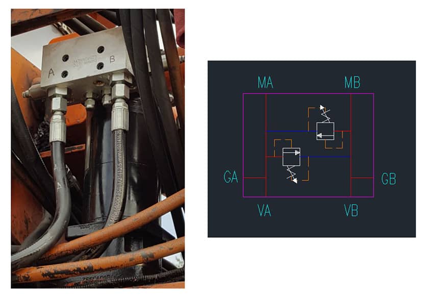
GA and GB were monitored throughout the testing.
Connected to VA and VB above were dual counterbalance valves. After removing this valve assembly from the circuit, everything worked beautifully (except for the counterbalance function of course). At this point, it was obvious there was a plumbing or counterbalance valve issue.
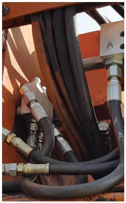
Counterbalance valves are mounted on the left in this image.
Schematic representations of individual components are generally available on manufacturer websites, so one was located for this part. It was determined that the actual plumbing resembled the following:
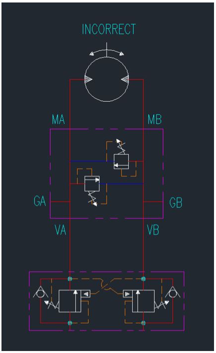
A counterbalance valve is supposed to meter the flow out of the motor, not the flow in. Therefore what is shown in the above schematic is incorrect.
The question still remained: Why did the motor turn before the oil heated up but cease to function once it was hot?
Viscosity (resistance to flow) usually decreases as temperature increases except in special formulations. A fluid with a high viscosity will create a larger pressure drop through a given restriction than a fluid with a lower viscosity.
In the dual counterbalance valve shown, each spool is actuated by a pressure signal from the opposite side of the circuit. At first, the cold and viscous oil created enough of a pressure drop over the check valve on the output side to open the spool on the input side. When the oil heated up, a smaller pressure signal was created and was not enough to open the spool on the input side. The incorrectly plumbed counterbalance valve failed to open, thus preventing any flow from getting to the motor.
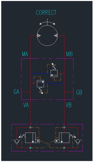
Once the plumbing was corrected, the motor turned freely and predictably. The reservoir also maintained a much lower temperature because oil was not being forced through an unnecessary restriction created by the partially shifted spool. In this case, we can infer that there was approximately a 1200 psi pressure drop created by the incorrect plumbing before the machine heated up. That’s system pressure (1500psi) minus gauge pressure (300psi). That will create a lot of heat!
Another Example
A hydraulically driven fan motor is not spinning up to the expected RPM. A variable piston pump is providing flow directly to the fan motor. Plumbing a gauge into the inlet side of the motor reveals that pressure is not as high as expected. The first idea is to check relief valve settings. Increasing the relief valve setting had no impact on the pressure reading before the motor.
The next check is to plumb a flow meter into the motor inlet as well. The flow meter indicates that less than expected flow is being supplied to the motor. Since the pressure reading is below the relief setting and there are no alternate paths between the pump and the motor, we know that the pump must not be providing adequate flow to the circuit. We must take a closer look at the pump.
The pump was removed and disassembled onsite, only to find that a maximum displacement stop was inside the pump. This stop allows a higher displacement pump to be used in applications where less than nominal flow is required. This is convenient since a customer can stock one modular pump that will work for multiple applications. Removal of this stop allowed the pump to reach the proper maximum displacement when it received a pressure signal.
In summary (and hindsight), it seems that hydraulic troubleshooting is not all that complicated once the true cause is understood. It’s getting to that root cause that is a challenge. Especially when you’re cold, hot, rushed, covered in oil, or in a number of other less than ideal conditions. The best approach is to keep a level head and think through the circuit one component at a time.