Chris Hardy | May 9th, 2016
- Are more accurate and repeatable than valves or dampers and do not suffer from hysteresis. This allows controls to be more tightly tuned.
- Are more efficient. Power is proportional to flow multiplied by pressure; slowing a pump or fan and opening a valve or damper means the same flow may be achieved with less Δ-pressure. Savings can be significant – often less than half the power used with full speed motors.
- Reduce wear on ducts, pipes, valves, and dampers caused by excessive pressure drop.
- Reduce the strain on rotating parts during starts (extending life & reducing maintenance cost).
- Draw lower amperages during starts, reducing peak loads and voltage sag on switchgear.
- More operational data about the motor is available without additional instrumentation.
- May be over-sped (above 60 Hz) to increase the capacity of undersized equipment.
VFD Pumps
A boiler can greatly benefit by running Boiler Feedwater (BFW) pumps on VFDs. When run at a constant speed, BFW pumps force BFW valves to drop a wide range of pressures from BFWdischarge down to drum pressure. Aside from causing excessive wear on the BFW valve, this also makes drum level control more difficult.
VFD BFW pumps should use the following control scheme:
- Calculate the highest steam drum pressure of all boilers supplied by that set of BFWpumps.
- Add a constant pressure (usually 50-150 PSI) to that highest drum pressure.
- Apply a smoothing filter to that BFW discharge pressure setpoint.
- A PID loop with BFW discharge pressure (between where the BFW discharge lines come together, but upstream of any BFW valves or branches to those valves) as Process Variable (PV), and the smoothed & biased drum pressure as setpoint.
- Send the output of the PID loop to all BFW pumps as the speed reference.
- If no BFW pump is running, hold the PID loop output to the minimum speed.
- Some systems benefit from using a feed forward input based on the number of pumps running, so it jumps when a pump starts or stops. For example, this might be 15 Hz when no or one pump is running, 6 Hz when two pumps are running, and 0 Hz when three are running. The values should be adjusted to minimize BFW pressure disruption after a start or stop. The example values would drop the pump speed by 9 Hz (from wherever it had been) when a second pump starts, and by another 6 Hz when a third pump starts.
There is then a more consistent pressure drop across the BFW valve, making a more consistent and linear relationship between valve position and BFW flow.
Warning: Multiple Pumps
If multiple pumps run together into the same discharge header, they should all be matched and run the same speed. The only exception is if they have independent flow measurement and control for each pump. If matched BFW pumps are run at different speeds, it is possible to shift all flow to one pump so that the slower pump is spinning but not generating enough pressure to open its check valve. It would then rapidly overheat and destroy its seals.
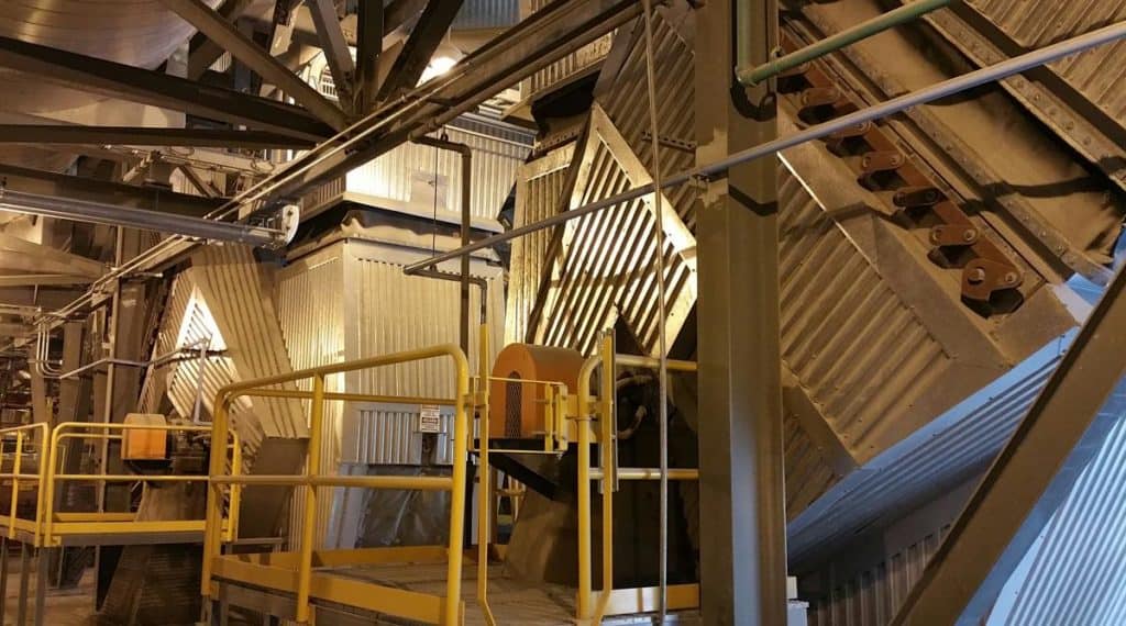
VFD Fans
Boilers feature large, powerful fans – smaller units may have just a forced draft (FD) fan; larger units will add induced draft (ID) fans, secondary air fans, overfire air fans, distribution air fans, etc… For fans such as distribution air which do not need much turn-down (the desired air flow is always 40%-100% of fan capacity), the traditional modulating inlet damper used to regulate flow / pressure may be replaced by attaching the motor to a VFD.
VFDs and Inlet Dampers Working Together
However, most fans require too much turn-down to eliminate inlet dampers. An ID fan must draw a small fraction of its capacity when first started (before an FD fan is started) to avoid pulling too much draft on the furnace. An FD fan may need to supply very low flow at low loads and/or when initially lighting the furnace. For these applications, modulating inlet dampers should be retained.
Inlet dampers can also close faster than VFDs can decelerate. Control on load reductions is more responsive with both a damper and VFD than with either alone.
Most possible control schemes either do not work well or are overly complicated. The ideal scheme for most VFD+damper applications is:
- A single PID loop. The PV might be median furnace draft pressure for an ID fan, duct pressure or FD flow for an FD fan, etc…
- Create two piecewise characterization tables (PWCT curves): one to fan speed reference and the other to damper position. The output of the PID loop will be the input for those curves.
- During commissioning, adjust the curves so that air / flue gas flow is roughly linear to % PID output. There are trade-offs between responsiveness and efficiency.
- A fan not needing much responsiveness (such as an FD fan or secondary air) could keep speed at minimum in the bottom half of the PID output range with its damper curve reaching 100% around the midpoint, then using fan speed to regulate the top half of the PID output range (some overlap in the middle is necessary).
- But a loop requiring responsiveness (such as an ID fan) should have both curves steadily increasing through the whole range.
VFD / Bypass Selection
If a VFD working in conjunction with a damper (or valve) has an “across the line” bypass option, there should be a third PWCT curve for the damper when in bypass / full speed mode (either bypass mode or forcing the VFD to run at full speed should trigger that curve). Once the other curves are tuned, run the fan in bypass (or with the VFD speed forced to maximum) and tune the bypass curve so that the PID output at every 10% increment produces approximately the same flow as it was in automatic speed control. This will mean the damper is more closed at each output than with a slower fan.
Minimum Speed
VFDs have minimum speeds that should almost always be set well above zero. Factors which may increase the minimum speed include:
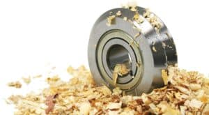
- Slinger rings in Babbitt bearings must spin fast enough to sling lubricating oil where it is needed. This might be as high as 20 Hz. This is not a factor for roller bearings or Babbitt bearings with pumped lubricant. Consider both the motor and load bearings.
- Most motors are cooled with an integral fan attached to the shaft. The motor must run fast enough to establish minimum cooling air flow. For fans, this can be fairly slow because their loads (and amps) are minimal when running slow, reducing heat production – 6 Hz is often a good minimum for those applications. But motors with high torque at slow speeds may need a higher minimum for cooling purposes. Sealed motors designed to run without a cooling fan and motors with a separate constant speed motor for a cooling fan may run all the way down to zero speed unless other factors raise the limit.
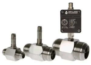
- Pumps need to move liquid when running. If there is a flow meter or switch to trip the pump on low flow, minimum speed is not a requirement – but if not, the minimum speed should be set to ensure there is some flow through the pump. Pumps discharging into high-pressure headers may need very high minimum speeds, sometimes above 50 Hz.
The minimum speed should be set both in the controller logic and in the VFD configuration.
VFD-Rated Motors
VFDs produce an output which approximates a sine wave, but consisting of discrete steps. Those “imperfections” in the sine wave induce extra current in the motor and cause slightly more heating than would be generated running across the line. Motors to be driven by VFDsmust be designed to handle the extra current and heat. Almost all modern motors are designed for VFDs, but if retrofitting an old system, make sure the motors are properly rated. They may need replacing or de-rating.
Overspeeding
VFDs may be configured to over-speed motors (run faster than 60 Hz). This is a possible solution for undersized equipment. There are many considerations before overspeeding, including:
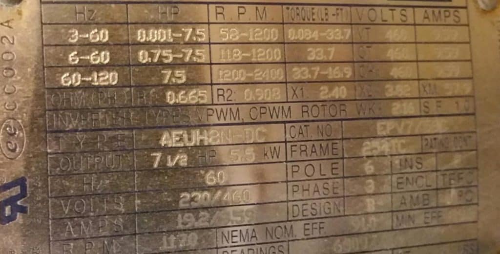
- Motor, gearbox, and load bearings must be able to handle the higher speeds. Nameplates (such as the one shown above, on a motor designed to be oversped to 120 Hz) sometimes show maximum speeds above 60 Hz. But most standard motors just list the limits for 50 and/or 60 Hz – in that case further information from the manufacturer may be necessary.
- Every piece of rotating equipment will undergo higher stresses from angular inertia.
- Motor amperage must still not be allowed to run above full load amps (FLA) steady state.
- Fans and pumps may lose efficiency when oversped.
VFD Speed Reference Units
Many systems are configured for VFD speed reference and feedback in %. I do not like using % because it doesn’t match the VFD display (which is usually in Hz), and it is ambiguous (% of maximum motor speed does not match % capacity of the system). Similarly, RPM is ambiguous – is it the RPM of the motor or of the driven component after gearboxes and sheaves?
I prefer to handle VFD speeds in Hz so there is no ambiguity, and the values on HMIs can be directly compared to values on VFD displays.
Summary
Special considerations are needed to run larger motors (such as fans and BFW pumps) on VFDs. When properly designed and controlled, VFDs can improve boiler efficiency, performance, tuning, and maintenance costs.