David Saunders | November 21st, 2016
Jerky and inconsistent control happens when two or more functions are actuated that have different pressure demands. This is a common situation for people who have inexpensive and/or basic valving. This can be addressed well with pressure compensation inside the valve.
However, if you have to downsize your pump, such as when you downsize an engine in an effort to make Tier 4 more affordable, it is possible to unexpectedly saturate your pump if you do not carefully analyze flow requirements. Pre and post-compensation act differently in a saturated condition and you need to consider what’s going to happen in this situation.
Why You Have Jerky Motion
Paul Badowski’s recent blog covers the basics of variable displacement pump controls. Load sense pump control is a commonly selected feature among mobile equipment manufacturers. However, taking full advantage of this type of pump control requires more than just a premium pump. It requires intelligent circuit design and the ability to communicate the “load sense” signal from any of the loads that you would like the pump displacement to be affected by.
A system with multiple varying loads will normally have a consolidated valve bank through which flow will pass and be distributed. Assuming the valve bank is load sense equipped (don’t forget this or your load sense pump is useless!), the pump control will receive the pressure signal from the load with the highest induced pressure. (For a valve to be “load sensing,” it will contain a series of shuttle valves and a port to send the load sense pressure signal back to the pump).
When just one function at a time is actuated, that pressure signal will be communicated to the pump, the pressure will build, and the function will work smoothly. In many cases, however, these systems will have widely varying loads on functions that need to work simultaneously. One cylinder could encounter 3000 psi while another will only ever see 500 psi. When two functions with different pressure demands are actuated at the same time, things get a little more complicated.
In this case, the pump would adjust its displacement until the highest pressure signal is matched. That pressure will exist throughout the entire system as long as the load is maintained. This means that for the lower pressure functions, there will be a pressure drop across the main directional spool equal to whatever the difference is between the highest load pressure and the local load pressure. The disadvantage is not just extra heat, but a change from smooth to jerky actuation due to the pressure drop across the spool.
With proportional spool valves, the spool is really acting as a variable flow control. This is a key feature with certain types of machines that depend on a user’s “feel” for the work they are doing. When the silky smooth control of a function changes to jerky and unpredictable, operators start making mistakes and can lose confidence. This translates to less work done and less profitability. Don’t try to cut valve cost up front and end up costing more in productivity! The purchasers may love you initially, but everyone else down the road will be cursing your name.
In this scenario, there is no way around the aforementioned heat generation as it is due to the pressure drop. There is, however, a way around the spool jerkiness. The answer is to move the pressure drop somewhere other than across the main spool. This can be accomplished by adding another spool adjacent to the main spool that will handle the majority of the pressure drop. This is illustrated schematically below:
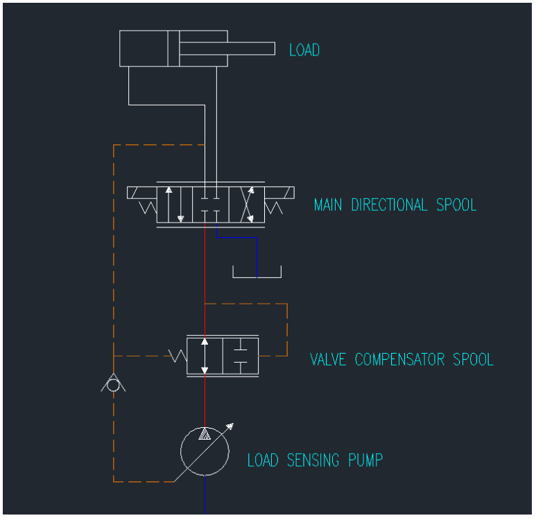
Compensated Valve Spool (Pre-Comp)
How Pre-Compensation Works
The valve compensator spool shown above is piloted from either side of the main directional spool. This means that it will constantly adjust itself so that the pressure drop across the main spool will always be equal to the spring that is offsetting the compensator. The method illustrated above is one way of compensating a valve for smooth operation with widely varying loads. It is known as Pre-Compensation because the compensator spool is upstream of the main spool and takes pilot signals from each side of the main spool.
As technology improves, we look to accomplish more with less energy. This leads us to downsize pumps and prime movers to the smallest size they can possibly be while still accomplishing the task. This sometimes results in saturating the pump, or demanding more pump flow than can be created by the system pump. But how does a load sensing valve perform when the limits of available pump flow are reached? By flow sharing. Don’t forget to do your homework before downsizing the source of flow or prime mover or you could end up with a more costly end result if not properly implemented. As Tier 4 becomes more and more relevant, so will the concepts of pre and post compensation.
How Post-Compensation Works
A pre-compensated valve does not perform well in a saturated flow situation. If multiple pre-compensated valve sections are open, then the highest pressure functions will lose flow and act sporadically. This is because of the fundamental fact that flow will always follow the path of least resistance. An answer to this problem is post-compensation. Its purpose is still to maintain a fixed pressure drop over the main control spool, but it is positioned downstream of the main spool and receives pilot signals from different sources.
One side of each post-compensating spool will always receive the same pressure signal as all other post-compensating spools, equal to the highest load-induced pressure. The other side of the compensator spool receives a pilot signal from between it and the main spool:
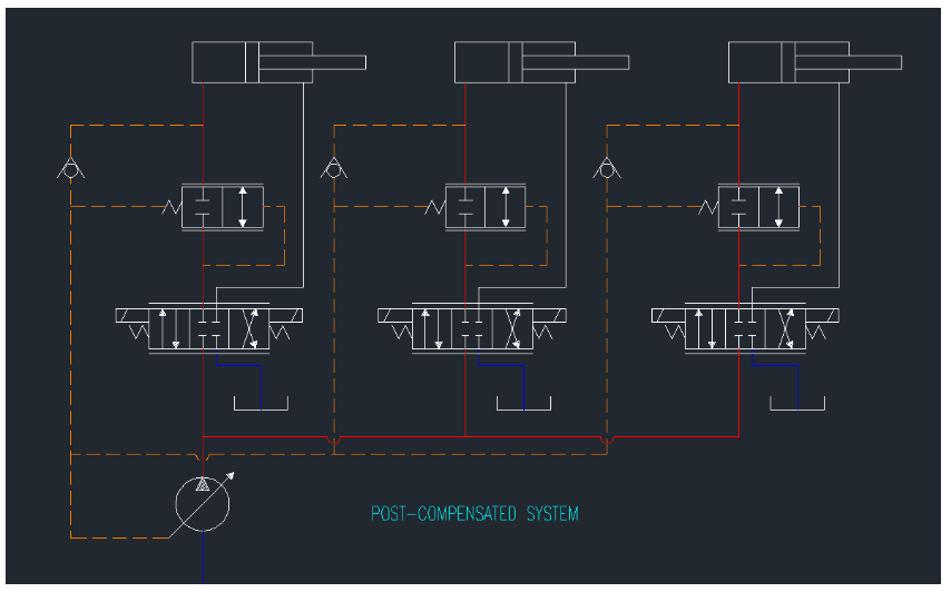
Post Compensated circuit, 3 working sections
The end result of this design is that regardless of the load induced pressure, each compensator forces identical upstream pressure to exist. This means that the path of least resistance when the pump is saturated is actually all paths equally. If the pump is only able to create 75% of the desired flow, then each function will slow down by 25% regardless of individual load characteristics. Take a look at the location of the check valves in the above schematic compared to the pre-compensated circuit below:
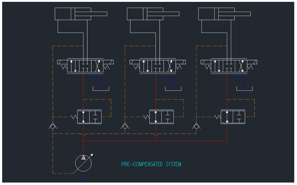
Pre-Compensated circuit, 3 working sections
How to Select the Correct Valve
This discussion should make clear the fact that for general flow sharing where all functions have equal priority, post compensated valves are the way to go. What if we want to give priority to a certain function, such as steering, a saw motor, or a swing function that absolutely must maintain speed? Don’t make the mistake of forgetting about the priority of functions or you could have some serious liability on your hands.
Eaton’s CLS series of valves has a unique design capability in that pre and post compensated valve sections can be combined in the same valve bank. This will result in the pre-compensated section always having priority flow in a saturated condition because it operates independently of the other load pressures. All other sections will lower proportionally.
Walvoil DPX valves assure priority by reducing the compensator bias spring. This ensures the priority function maintains the selected flow during saturation. All other functions reduce flow in a coordinated manner. This option is achieved using the same section body for either standard or priority function.
Cross Company has extensive experience in the implementation of load-sensing and flow-sharing valves. Don’t spend your money on the wrong components – when you have uncertainty, we are here to help.